


Understanding Accuracy and Resolution for Magnetic Angle Sensors
DOWNLOAD PDF


Get valuable resources straight to your inbox - sent out once per month
We value your privacy
Introduction
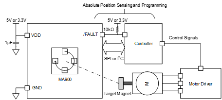
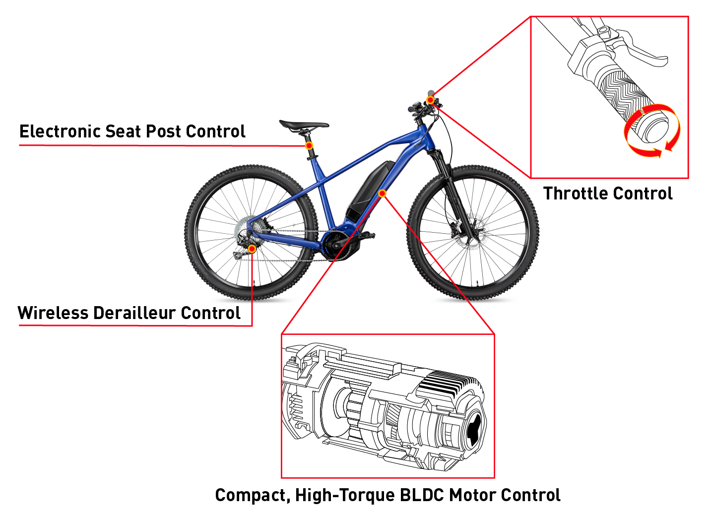
Magnetic position sensors, especially magnetic angle sensors, are the fundamental building blocks of countless motion-control applications that necessitate precision positioning. These sensors are pivotal in a wide range of industries, from automotive and robotics to consumer electronics and medical devices, underscoring their universal appeal and importance (see Figure 1).

Figure 1: Magnetic Position Sensor Applications
However, to realize their full potential and utility, one must delve into two crucial parameters that govern their performance: accuracy and resolution. Although these terms are often used interchangeably, they represent distinct — albeit related — concepts in any measuring system. This comprehensive article aims to shed light on these parameters, explain how they impact the performance of magnetic position sensors, and provide guidance on optimizing these factors.
Understanding Accuracy and Resolution
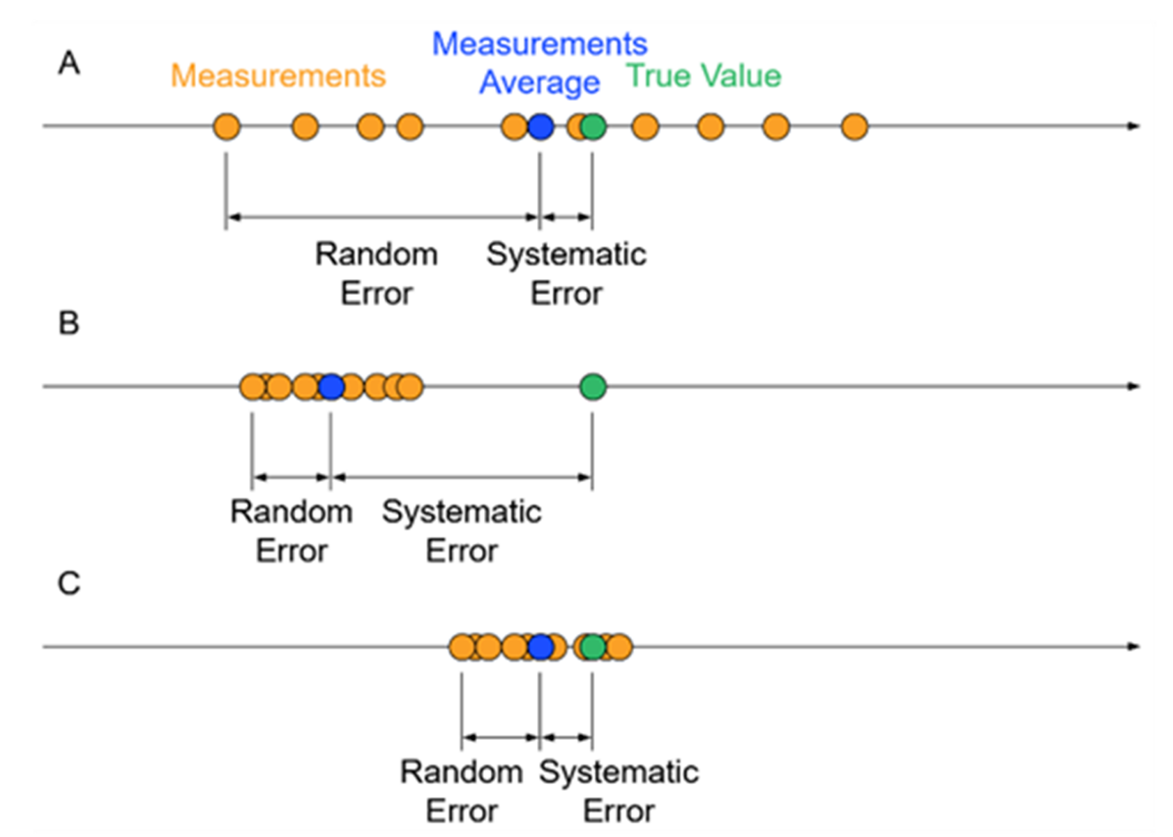
Within the context of measurement and instrumentation, accuracy refers to the closeness of a measured value to the actual or true value of the quantity being measured. For magnetic position sensors, accuracy is the measure of how precisely the sensor’s angle measurement reports the actual angle. Accuracy is a way of understanding how closely the sensor’s read position corresponds to the actual position, with a high accuracy sensor producing readings that are very close to the true position.
On the other hand, resolution signifies the smallest change in the measured quantity that a sensor can detect. For magnetic position sensors, resolution is the minimum angle change that the sensor can ascertain. Resolution is essentially a measure of the sensor’s sensitivity to minute changes in the position. A high-resolution sensor can detect even the smallest changes in position, providing a detailed, granular measurement.
One critical distinction is that a high resolution does not inherently imply high accuracy. A sensor might be highly sensitive to minute changes, meaning it has a high resolution, but it could still be inaccurate if its measurements consistently veer away from the true value. Conversely, a sensor can be highly accurate and consistently provide measurements close to the true position, but it may have low resolution, which means it is unable to catch small changes in position.
This paradox underpins the complexity of designing and implementing magnetic position sensors. Engineers must strike a balance between resolution and accuracy to achieve optimal performance, depending on the specific needs of the application at hand.


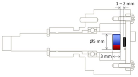
Maximizing Sensor Performance: the Tradeoffs
To maximize the performance of a magnetic position sensor system, it is critical for engineers to understand how to quantify accuracy and resolution. More importantly, they must comprehend what system parameters can be tweaked to enhance accuracy or resolution, and they must understand how manufacturers represent these parameters in their datasheets.
Unfortunately, every improvement or enhancement comes at a cost, and the same applies to increasing resolution and accuracy. Striking the right balance between these two parameters requires careful consideration of various tradeoffs.
To enhance resolution, it is important to minimize noise. A window averaging output filter can be used to decrease noise, thus improving resolution. This filter works by smoothing out the random fluctuations in the sensor’s readings, helping to deliver more consistent and accurate results.
However, while an averaging filter increases resolution, it lowers the dynamic bandwidth, which means that the system’s reactions to accelerations will be delayed proportionally to the bandwidth reduction. If the filter window is set too wide, it can lead to a poor step response and instability in a servo control loop, negatively impacting the system’s performance. A basic rule of thumb for Hall-based magnetic angle sensors is that to achieve an extra half bit of resolution, the dynamic bandwidth will be halved.
On the other hand, increasing accuracy (or reducing integral nonlinearity (INL)) can be achieved through calibration. Calibrating the sensor output after it has been installed in its application can help counteract the effects of mechanical tolerance stack-ups and magnet imperfections, leaving only temperature drift as the primary INL contributor. The tradeoff here, however, is cost. Calibration requires time, resources, and specialized knowledge, which translates into increased production costs. For this reason, calibration might not be a feasible option for all applications, especially those where cost is a significant concern.
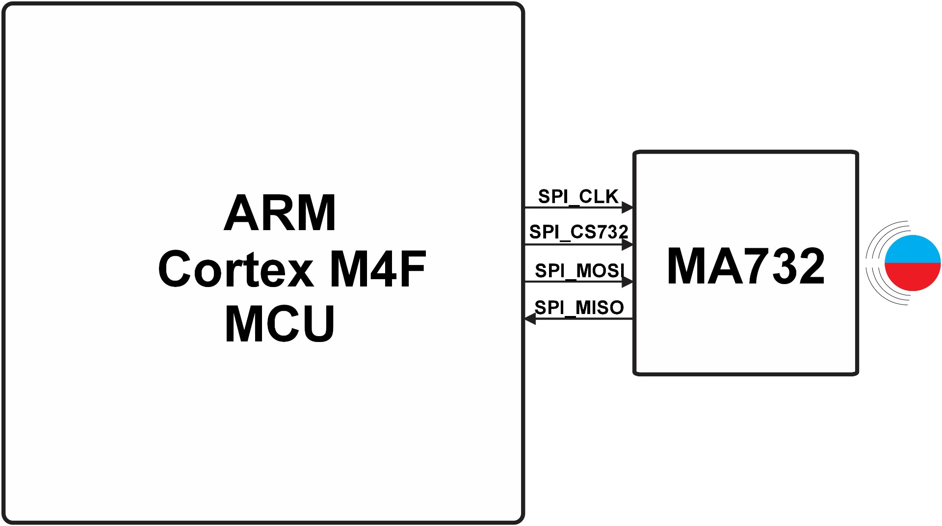
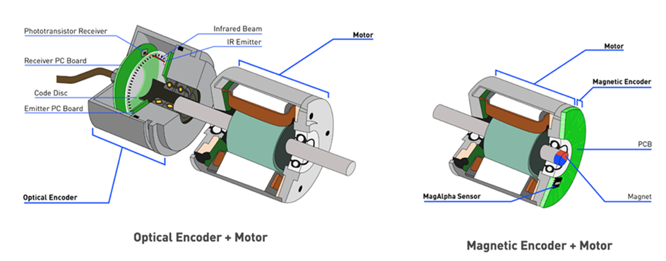
In situations where high resolution and high bandwidth are required, or where an extremely low INL is critical (below 0.1°, for example), specific solutions like the MA600A can offer an excellent balance between performance and cost (see Figure 2). The MA600A provides a higher bandwidth and resolution than Hall-based solutions, and it is significantly less expensive than the next best alternative, an optical encoder. Because the MA600A is tunneling magneto-resistance (TMR) based, its noise is significantly lower than a Hall-based solution; in addition, the MA600A’s noise profile is not Gaussian, unlike traditional Hall-sensors. These factors greatly reduce the bandwidth tradeoff in TMR.
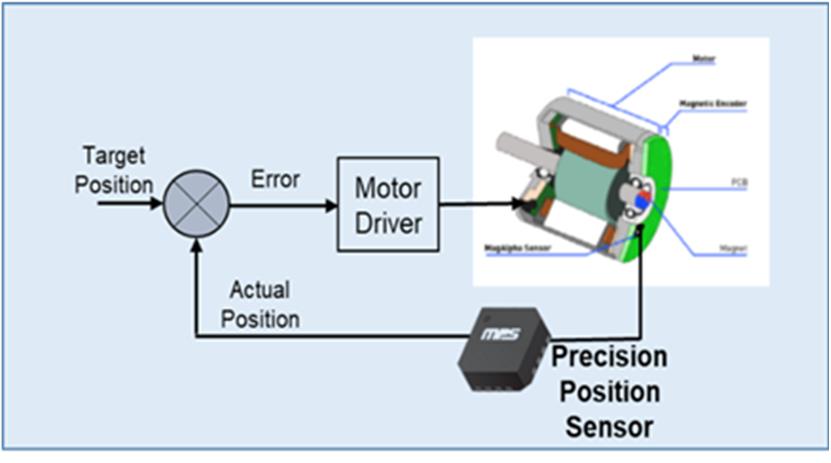
Figure 2: The MA600A Solution
Accuracy and Resolution Quantified
Manufacturer datasheets provide detailed information on not just the sensor’s accuracy and resolution specifications, but also other critical parameters, such as the operating temperature range, supply voltage, quiescent current, and magnetic field strength range. Not all datasheets are created equal, however, and one must be careful when comparing specifications.
For example, some manufacturers specify resolution based on a 1σ noise range, meaning that the minimum angle change can be detected only 68% of the time. Meanwhile, MPS specifies resolution as a ±3σ noise level (see Figure 3). This guarantees that the resolved difference between two angles will be correct 99.7% of the time. Not all manufacturers are so conservative, and it is easy to make the resolution look higher by ignoring the 3σ requirement.
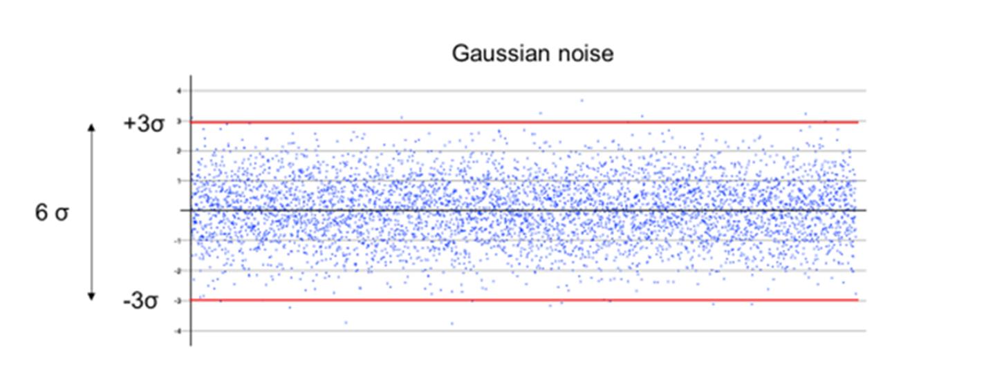
Figure 3: ±3σ Noise Level
Accuracy (or INL), on the other hand, is relatively straightforward and there is a less leeway to disguise the actual sensor performance. One thing to consider is the temperature range across which the specification is listed. As mentioned previously, calibration can reduce the INL created by mechanical or magnetic tolerances, but it is much more difficult to calibrate against temperature drift.
Conclusion
Choosing the right magnetic position sensor for a given application involves understanding the intricate tradeoffs between accuracy, resolution, and other system parameters. It also requires an understanding of how these parameters can be optimized to deliver the best possible performance.
By understanding the key concepts of accuracy and resolution and how they apply to magnetic position sensors such as the MA600A, engineers can make informed decisions when selecting sensors for their systems. This knowledge helps in optimizing performance, keeping costs under control, and ensuring the successful execution of their designs.
In the ever-evolving world of technology, where precision and accuracy are paramount, understanding the nuances of magnetic position sensors is invaluable. Armed with this knowledge, engineers are better equipped to navigate the complexities of the digital world and harness the full potential of magnetic position sensors in a wide range of applications.
_______________________
Did you find this interesting? Get valuable resources straight to your inbox - sent out once per month!
アカウントにログイン
新しいアカウントを作成