How to Avoid Unstable Power Supply Shutdown Processes

Get valuable resources straight to your inbox - sent out once per month
We value your privacy
Introduction
The electrical appliances we use in our daily lives — from lights to computers — typically go through a shutdown process when they turn off. Power supplies require stable shutdown processes that can control for unexpected overshoot. In a stable shutdown process, the power supply smoothly drops the input voltage (VIN) to 0V.
For a stable shutdown, there should a steady VIN drop, no negative output voltage (VOUT) overshoot, and no VIN or VOUT rebound. This article will discuss three unstable waveforms that can be observed during the power supply shutdown process. For the sake of this article, they will be designated as one of three classes: Class R (with a quick VIN and VOUT rebound), Class G (negative VOUT overshoot), and Class B (with a delayed VIN and VOUT rebound).
Class R Shutdown (Quick VIN and VOUT Rebound)
Figure 1 shows the Class R shutdown waveform. In a Class R shutdown, VIN steadily drops as the device shuts down, briefly increases during an energy spike, then begins to steadily drop again.

Figure 1: Class R Shutdown Waveform
There are two types of Class R waveforms, which are described below.
Related Content
-
WEBINAR

Maximizing Power Density of DC Fast-Charging Systems with an LLC Power Supply
Learn more about the charging infrastructure and see how MPS solutions can help your infrastructure
-
ARTICLE
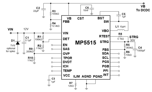
Planning for Sudden Power Failures with the MP5515
Explore MPS’s energy management solutions and learn how we can help power and protect your device
-
APPLICATION BLOCK
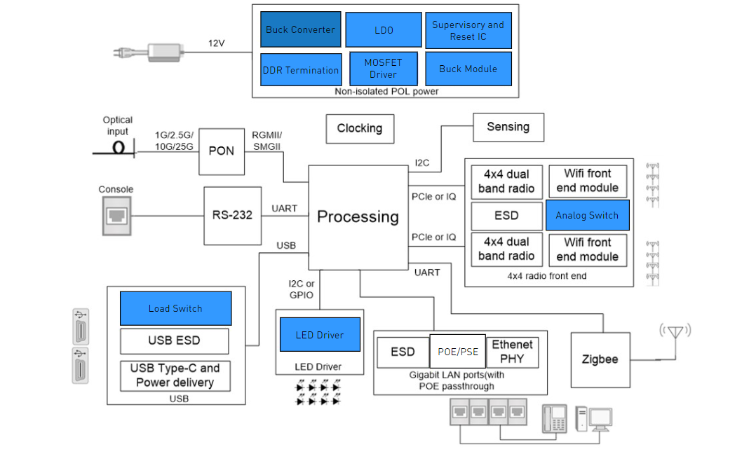
Optical Network Terminal (ONT) Units
MPS’s innovative, cost-effective solutions offer the best power management for your optical network terminal unit design
-
ARTICLE

Optimizing Power Supply Efficiency with MOSFET Selection
This article introduces how to select the appropriate HS-FET and LS-FET ratio through accurate mathematical modeling to optimize your power supply’s efficiency.
Class R Shutdown (Type I)
A Class R Type I shutdown occurs when the DC/DC converter restarts.
Consider a standard shutdown. If VIN drops to the chip’s turn-off threshold, the chip shuts down. VOUT drops during this process, causing the current to suddenly decrease. However, if the chip’s input line has nowhere to release the excess energy from the inductive reactance during this process, then VIN sharply increases.
If VIN exceeds the chip’s operating threshold, the chip resumes operation and results in a non-monotonous shutdown waveform. A Class R waveform is classified as Type I if there is a switch present on the SW side (see Figure 2).
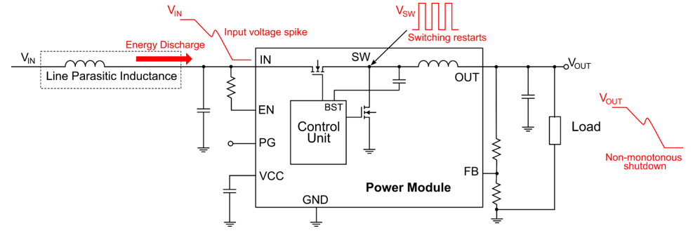
Figure 2: Line Parasitic Inductance of Class R Type I Shutdown
The Class R Type I waveform is relatively simple to prevent. The chip’s specifications provide the enable (EN) and VIN under-voltage lockout (UVLO) parameters. Figure 3 shows the enable and UVLO specifications for the MPM3683-7, a step-down power module.
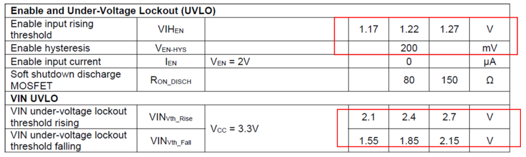
Figure 3: MPM3683-7 Specifications
With these specifications in mind, there are two methods to avoid an unstable shutdown, described below:
- Reduce the VIN bounce by optimizing input filtering, reducing input inductance, selecting a capacitor with a larger capacitance and smaller equivalent series resistance (ESR) and equivalent series inductance (ESL), and placing the input capacitor as close to the IC as possible.
- Select appropriate upper and lower voltage resistor dividers for EN, such that EN turns off when VIN drops to its UVLO threshold. This can prevent the IC from starting up again.
Class R Shutdown (Type II)
If the load is suddenly reduced, the excess energy stored in the integrated output inductor or the output line inductor cannot be released anywhere (see Figure 4). This can significantly increase VOUT for a short time.

Figure 4: Class R Type II Event
Figure 5 shows the Class G shutdown waveform. In a Class G shutdown, VOUT drops steadily, then drops rapidly past its target (called negative overshoot) before rising back up to its target value.
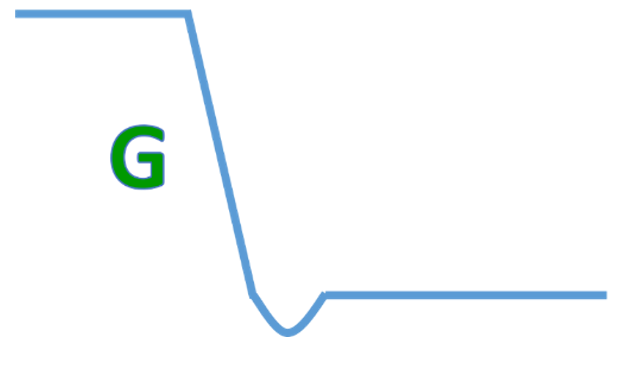
Figure 5: Class G Shutdown Waveform
Similar to Class R waveforms, Class G waveforms can be subdivided into two types.
Class G Shutdown (Type I)
If the buck circuit’s low-side MOSFET (LS-FET) does not turn off during shutdown, the inductor current continues to reverse. This situation is more common under no-load and light-loads conditions, and it can result in VOUT dropping too low.
To prevent this issue, the DC/DC converter typically adds zero-current detection (ZCD) during shutdown, then automatically turns off the LS-FET when it detects that the current has reached 0A (commonly called the ZCD point) (see Figure 6). This approach can effectively prevent negative overshoot during shutdown.
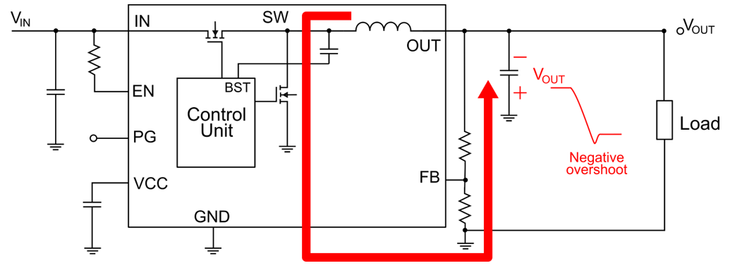
Figure 6: Preventing Negative Overshoot in Class G Type I
Class G Shutdown (Type II)
VOUT can experience negative overshoot due to the parasitic inductive reactance on the output line (see Figure 7). This type of shutdown is more likely to occur under heavy loads or during output short-circuit faults.
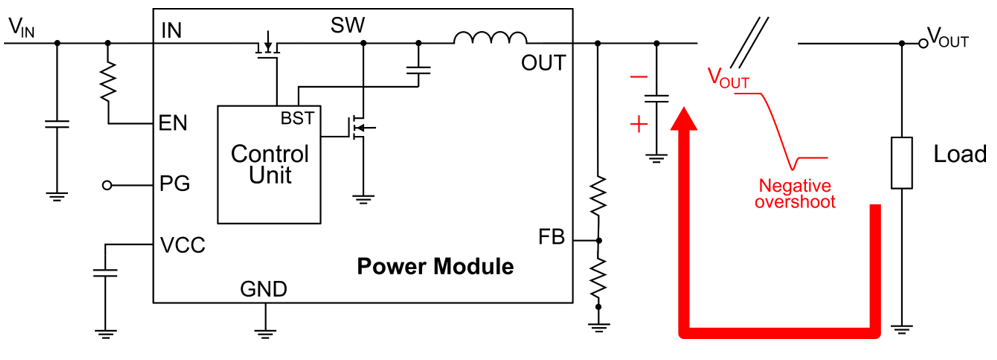
Figure 7: Reduce Parasitic Inductive Reactance of Class G Type II
The output line’s inductive reactance must be minimized to prevent Class G Type II shutdown. In addition, the load terminal’s capacitance should be increased.
Class B Waveform (Delayed VIN and VOUT Rebound)
Figure 8 shows a Class B shutdown waveform, which occurs under heavy loads. In a Class B waveform, both VIN and VOUT fall sharply, rise for a short period of time, then remain stable (as with VOUT) or fall again (as with VIN). Both scenarios are referred to as a rebound.
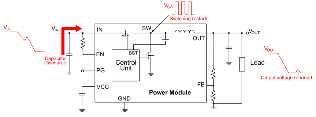
Figure 8: Class B Shutdown Waveform under Heavy Loads
Class B waveforms look similar to Class R waveforms, but Class R waveforms are due to the line inductance, and Class B waveforms have a much later rebound. After the first shutdown, VOUT and VIN typically rebound in microseconds with Class R shutdowns; however, VOUT and VIN may not rebound for up to tens of milliseconds in Class B shutdowns.
The dielectric absorption effect leads to the Class B waveform. If the input capacitor’s discharge current is large then suddenly drops to 0A, the dielectric in the capacitor slowly releases some of the previously absorbed charges. Once the discharge current reaches the chip’s start-up voltage again, VOUT rebounds.
To prevent a Class B shutdown, a chip can be powered off through EN, similar to the method used for Class R Type I shutdowns. Select the VIN under-voltage protection (UVP) threshold and hysteresis to ensure that EN stays off. Then the VIN rebound does not exceed the chip’s power-on threshold and lead to an accidental restart. In addition, static loads can be added to consume any excess charge.
Conclusion
This article explored three different types of shutdown waveforms (Class R, Class G, and Class B) related to the power supply shutdown process, with the intent of improving stability and preventing negative overshoot. These classes were also further subdivided, depending on the excess energy and loads conditions.
For more details, explore MPS’s robust selection of step-down power modules.
_______________________
Did you find this interesting? Get valuable resources straight to your inbox - sent out once per month!
Technical Forum
 Latest activity a week ago
 2 Comments
Latest activity a month ago
2 Comments
Latest activity a month ago
4 Comments
2 Comments
Latest activity a month ago
2 Comments
Latest activity a month ago
4 Comments
Log in to your account
Create New Account