


Designing a Peak Power-Shaving Solution for AI Server Applications
DOWNLOAD PDF


Get valuable resources straight to your inbox - sent out once per month
We value your privacy
Introduction
The power requirements of AI servers are evolving due to the rapid development of AI systems. When AI training starts, the AI GPU power demands can require short bursts of power that exceed the GPU’s idle-state power by 10 times. These power bursts can cause a large inrush current at the server’s power supply units (PSUs) or even overload the PSUs.
However, most AI training periods last for a relatively short time, then the GPUs stay in their idle state for a much longer period. So while these short bursts may exceed the peak capability of server power systems, they do not significantly change the average power requirements. A higher-power PSU module meets this peak power requirement, but it is not cost-effective and takes more shelf space.
With this in mind, new AI server power supply unit demands can be addressed with a dedicated peak-shaving circuit to shave the peak power inrush to the PSUs, that stores bus power during the low-power GPU idle states and supplements bus power when the GPUs are in training mode. This article will describe how to create a peak-shaving circuit for AI servers.
Figure 1 shows a simplified system block diagram for a peak-shaving circuit. A peak-shaving circuit usually consists of a bidirectional charger to charge from — or discharge to — the PSU bus according different GPU states, a supercapacitor array to store the energy from the PSU while the GPU is in an idle state, an analog front-end (AFE) to monitor the status of each capacitor cell, and an optional active balancer to provide faster balancing speed for the supercapacitor array when compared to the passive balancer in the AFE.
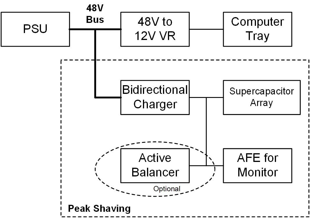
Figure 1: System Block Diagram of the Peak-Shaving Circuit
Figure 2 shows a power flow example for the peak-shaving circuit. The positive current denoted in the blue area refers to discharging, while the negative current denoted in the yellow area refers to charging. When training starts, the server power system’s load is heavy, and the supercapacitors discharge to supply the GPUs’ peak power requirements. In an idle state, the supercapacitors charge with a relatively low current to store excess energy from the PSU.
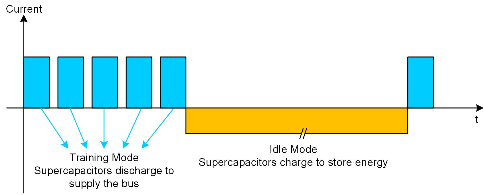
Figure 2: Power Flow of the Peak-Shaving Circuit
Bidirectional Charger Solution Using the MP2769
During the charging and discharging process, the supercapacitors’ voltage may be higher or lower than the 48V bus voltage. To handle the charging and discharging of the supercapacitors, designers often need a buck-boost converter.
The MP2769 is a 60V, I2C-configurable, bidirectional buck-boost charger controller. The device controls the buck-boost converter between 48V bus and the supercapacitors in the peak-shaving circuit according to different GPU status. When training starts, the MP2769 discharges the supercapacitors to supply the bus load, then stores power back to supercapacitors in GPU’s idle state. Compared to a traditional DSP-based solution, the MP2769 eliminates the need for an external gate driver of the switching FETs, an input and output current-sense circuit, and DSP coding for loop compensation, which reduces the complexity of the design work. These features make the MP2769 an excellent candidate for peak-shaving applications.
Figure 3 shows a typical application circuit of the MP2769, in which the switching power FETs are driven directly by the MP2769.
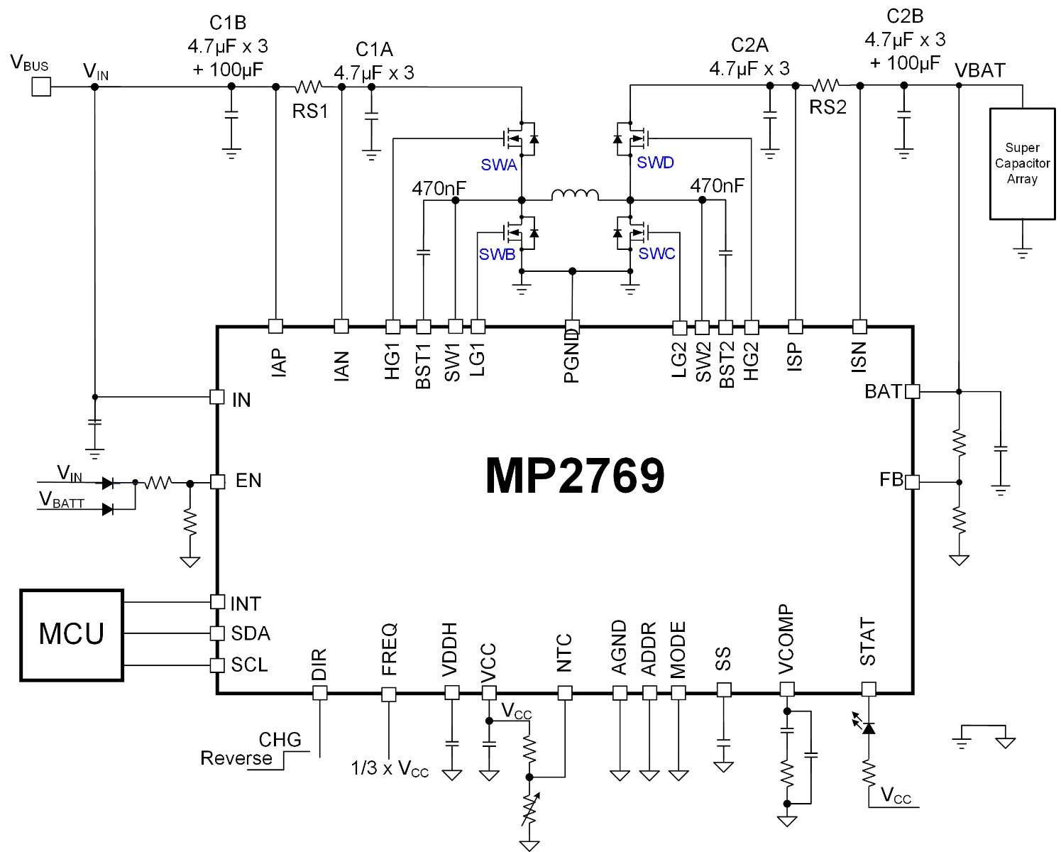
Figure 3: MP2769 Typical Application Circuit
In a peak-shaving application, the idle time is typically much longer than the training time. This means that the supercapacitors can have ample time to be charged, but they need to discharge within a relatively short time to supply the GPUs with sufficiently high peak power. To facilitate this process, designers typically need to use multiple modules in parallel to discharge power but only one module to charge power. Figure 4 below shows this architecture.
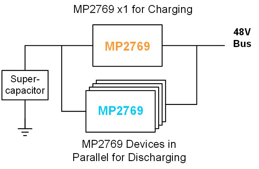
Figure 4: Multiple MP2769 Connections for the Peak-Shaving Circuit
To enable these modules to transition between charging and discharging automatically according to the AI training status, set the minimum input voltage threshold (VIN_MIN) of the charging module slightly below the normal bus voltage. Meanwhile, set the output voltage (VOUT) of the discharging modules below VIN_MIN. For example, with a 48V bus voltage (VBUS), set VIN_MIN to 47V and VOUT to 46V.
When the GPU is in an idle state, the PSU’s load is light. Because VBUS is 48V, the charging module charges the supercapacitors from the bus because VBUS exceeds VIN_MIN. The discharging modules remain in an idle state while VBUS exceeds VOUT. When training starts, VBUS begins to drop due to limited PSU power. When VBUS drops below VIN_MIN, the charging module stops charging; if VBUS drops down to VOUT, the discharging module starts switching and works with the PSU to supply the peak power demand for the GPUs. Figure 5 shows this process.
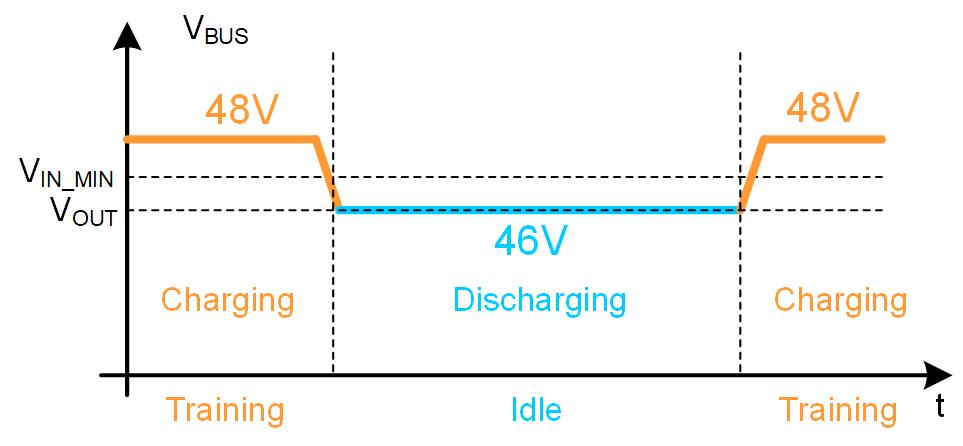
Figure 5: Charging/Discharging Transition





AFE Solution for a Supercapacitor Array Using the MP2793
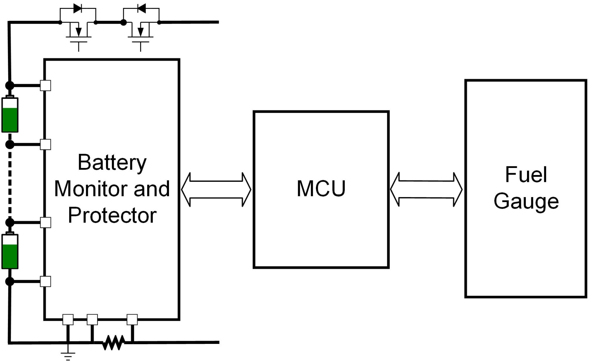
The supercapacitor array in the peak-shaving circuit is typically comprised of multiple supercapacitors connected in series. To ensure that the supercapacitor array runs safely, it is vital to monitor the status of each cell in the array, especially when the capacitance variation between each supercapacitor can cause a voltage imbalance for each cell after a long runtime. To solve this, we need a dedicated AFE to monitor the status of each capacitor and provide voltage balancing for each cell.
The MP2793 is an analog front-end (AFE) monitoring and protection solution for 4-cell to 16-cell Li-ion batteries that can be used in supercapacitor systems. It provides complete monitoring and protection functions for the cell voltage, charge/discharge current, pack voltage, and cell temperature, which ensures that the supercapacitor array runs safely in the peak-shaving circuit. It also provides passive balancing to resolve potential imbalance issues for each capacitor cell after an extended runtime, so that
the voltage difference of each capacitor cell is within a safe and acceptable range to prevent the whole capacitor array from failing due to an imbalanced cell.
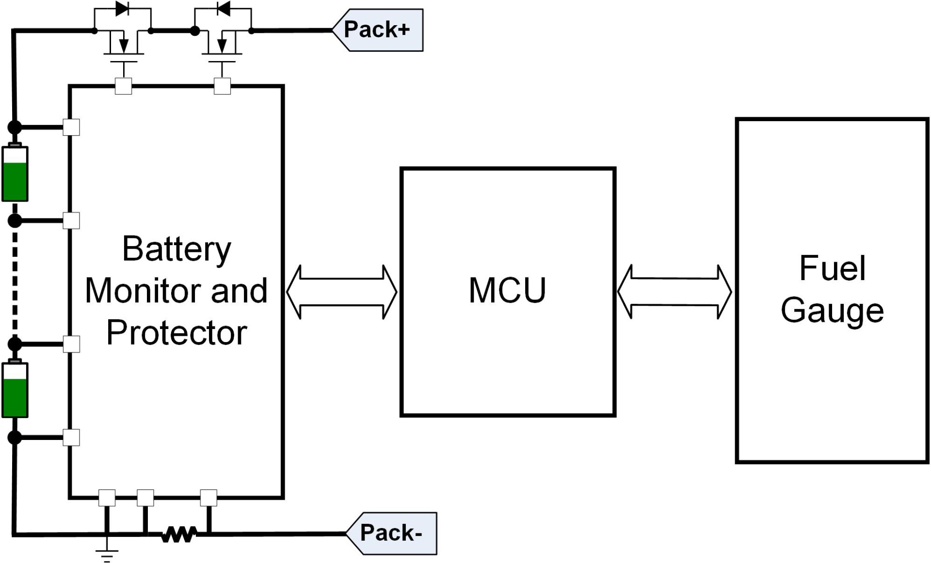
The MP2793 can be implemented as the AFE in the supercapacitor array of the peak-shaving circuit. Figure 6 shows the connection of the MP2793, supercapacitor array, and MCU. The MP2793 can report the supercapacitors’ voltage, current, and temperature info to the MCU in real time, balance the cell voltage to each cell connected in series, and cut off the protection FETs if any fatal fault (e.g. short-circuit, over- or under-voltage, over-temperature of the capacitors) occurs.
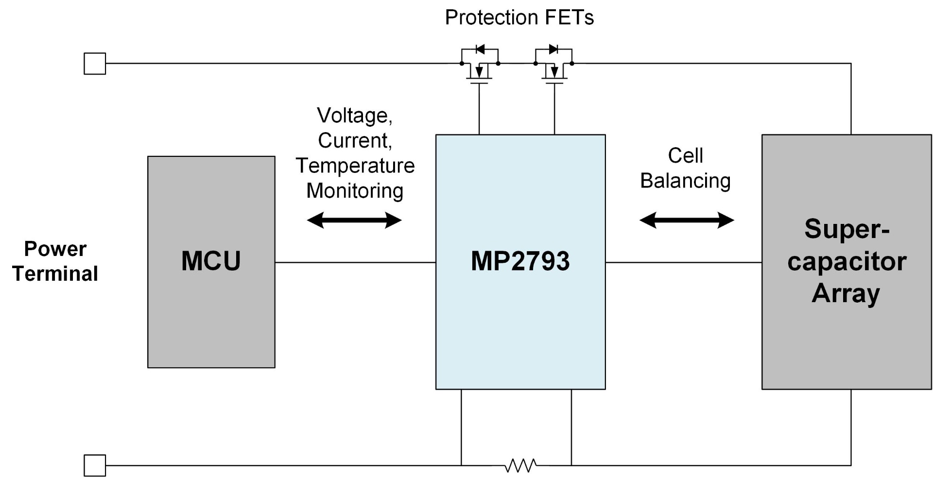
Figure 6: MP2793 Connection between Supercapacitors and MCU
Optional Active Balancer in a Peak-Shaving Circuit
Because the supercapacitors in a peak-shaving system are charged and discharged much more frequently than in a typical energy storage system (ESS), imbalanced capacitors impact these systems much more quickly. For a passive balancer, the balancing current is typically limited below 200mA due to thermal considerations. In this scenario, a traditional passive balancing method may not be able to provide a sufficient balancing speed to keep the voltage of each capacitor cell balanced. To solve this issue, designers can implement an active balancer to balance the capacitors more quickly.
The MP2645 is a 5-cell, stackable active balancer, with up to 3.75A of balancing current. It can support cascaded stack operation with up to 8 chips (33 cells). Compared to a passive balancer, it can provide a higher balancing current with better thermal performance, which makes it suitable for applications that require a faster balancing speed.
Figure 7 shows the proposed peak-shaving circuit using this active balancer.
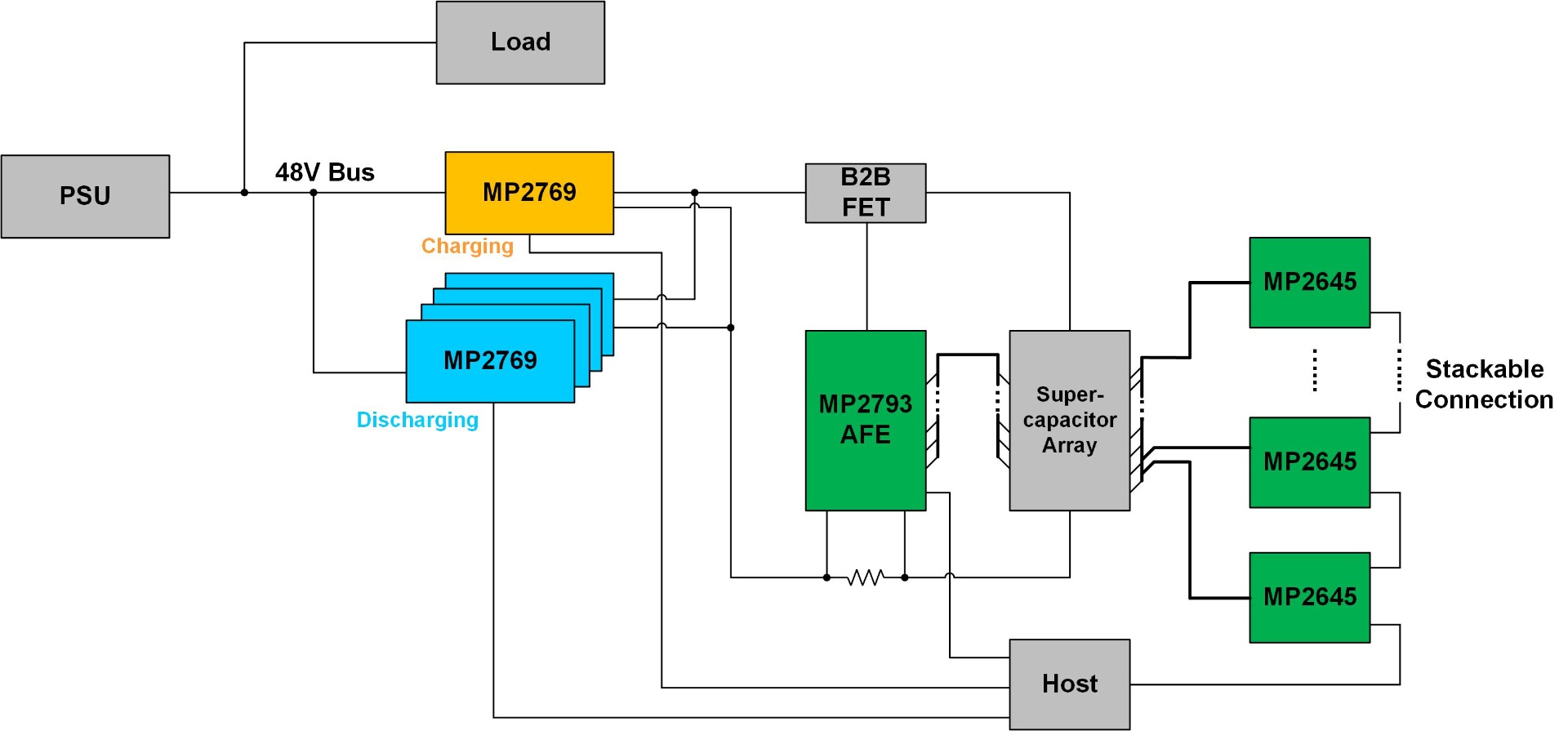
Figure 7: Peak-Shaving Application
Prototype of a Peak-Shaving Circuit with the MP2769 and MP2793
Figure 8 shows a prototype of the peak-shaving solution using the MP2769 and MP2793. This solution consists of three MP2769 modules, a MP2793 AFE board, a 16-cell supercapacitor array, and a fan for cooling. For the three MP2769 modules, one is set to charge mode, and the other two are set to discharge mode. When VBUS is high, the charging module (MP2769-1) switches to charge the supercapacitors, and the discharging modules (MP2769-2 and MP2769-3) are in an idle state. When AI training starts, VBUS drops and the MP2769-1 stops charging, while the MP2769-2 and MP2769-3 start discharging the supercapacitors to supply VBUS.
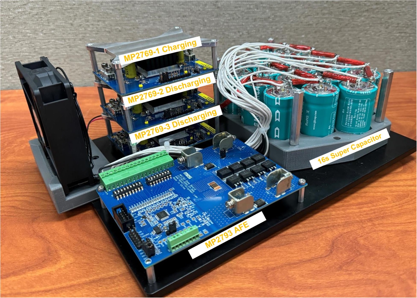
Figure 8: Prototype Peak-Shaving Circuit
Figure 9 shows a waveform for this peak-shaving circuit between charging and discharging transitions. Table 1 shows the settings for the modules.
Table 1: Charging and Discharging Transition Settings
| Modules | Mode | VIN_MIN | Charge Current (ICC) | VOUT | Output Current Limit (IOLIM) |
|---|---|---|---|---|---|
| MP2769-1 | Charge | 47V | 5A | - | - |
| MP2769-2 | Discharge | - | - | 46V | 5A |
| MP2769-3 | Discharge | - | - | 46V | 5A |
Figure 9 shows that when VBUS drops as training starts (denoted by the blue area), the MP2769-1 stops switching, and the MP2769-2 and MP2769-3 start switching to supply the bus load. When VBUS returns to 48V as the GPUs return to an idle state (denoted by the yellow area), the MP2769-2 and MP2769-3 stop switching, and the MP2769-1 starts switching to store the bus power to the supercapacitors.
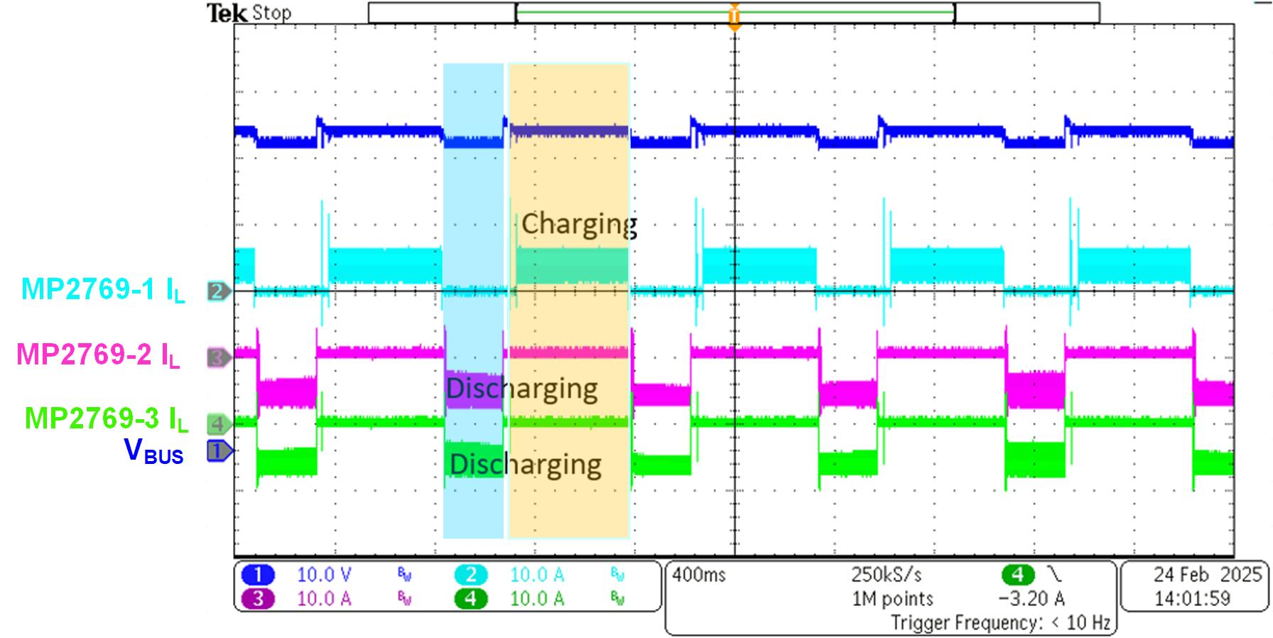
Figure 9: Peak-Shaving Circuit Charge and Discharge Transition
Conclusion
When AI training begins in AI servers, the GPUs and PSUs operate at full power for short time; the rest of the time, they work in light-load modes. In addition, peak power bursts during AI training can generate a large power inrush to the power grid. A peak-shaving circuit can help reduce power inrush to AI server power systems and meet the peak GPU power demands when AI training starts.
This article described how to design a peak-shaving circuit for the AI server applications. When designing this circuit, a highly integrated bidirectional buck-boost charger solution such as the MP2769 can discharge and charge the capacitor; meanwhile, a battery monitor and protector such as the MP2793 provides monitoring, protection, and cell-balancing to ensure that the supercapacitor array runs safely. Lastly, an optional active balancer (e.g. the MP2645) can offer much higher balancing current if a faster balancing speed is required. When working together, these parts are well-suited for building a peak-shaving solution. Explore MPS’s charger, battery monitor and protector, and active balancer devices learn more about battery management solutions for any application.
_______________________
Did you find this interesting? Get valuable resources straight to your inbox - sent out once per month!
Technical Forum
 Latest activity 2 days ago
 2 Comments
Latest activity a week ago
4 Comments
Latest activity 2 weeks ago
4 Comments
2 Comments
Latest activity a week ago
4 Comments
Latest activity 2 weeks ago
4 Comments
Log in to your account
Create New Account