Functional Safety in Non-Automotive BMS Designs

Get valuable resources straight to your inbox - sent out once per month
We value your privacy
Introduction
Battery-powered applications, which have become indispensable over the last decade, require a certain level of protection to ensure safe use. This safety is provided by the battery management system (BMS). The BMS monitors the battery and possible fault conditions, prevents any hazardous situation due to the battery or its surroundings, and ensures that there is an accurate estimation of the battery’s remaining capacity or the level of battery degradation.
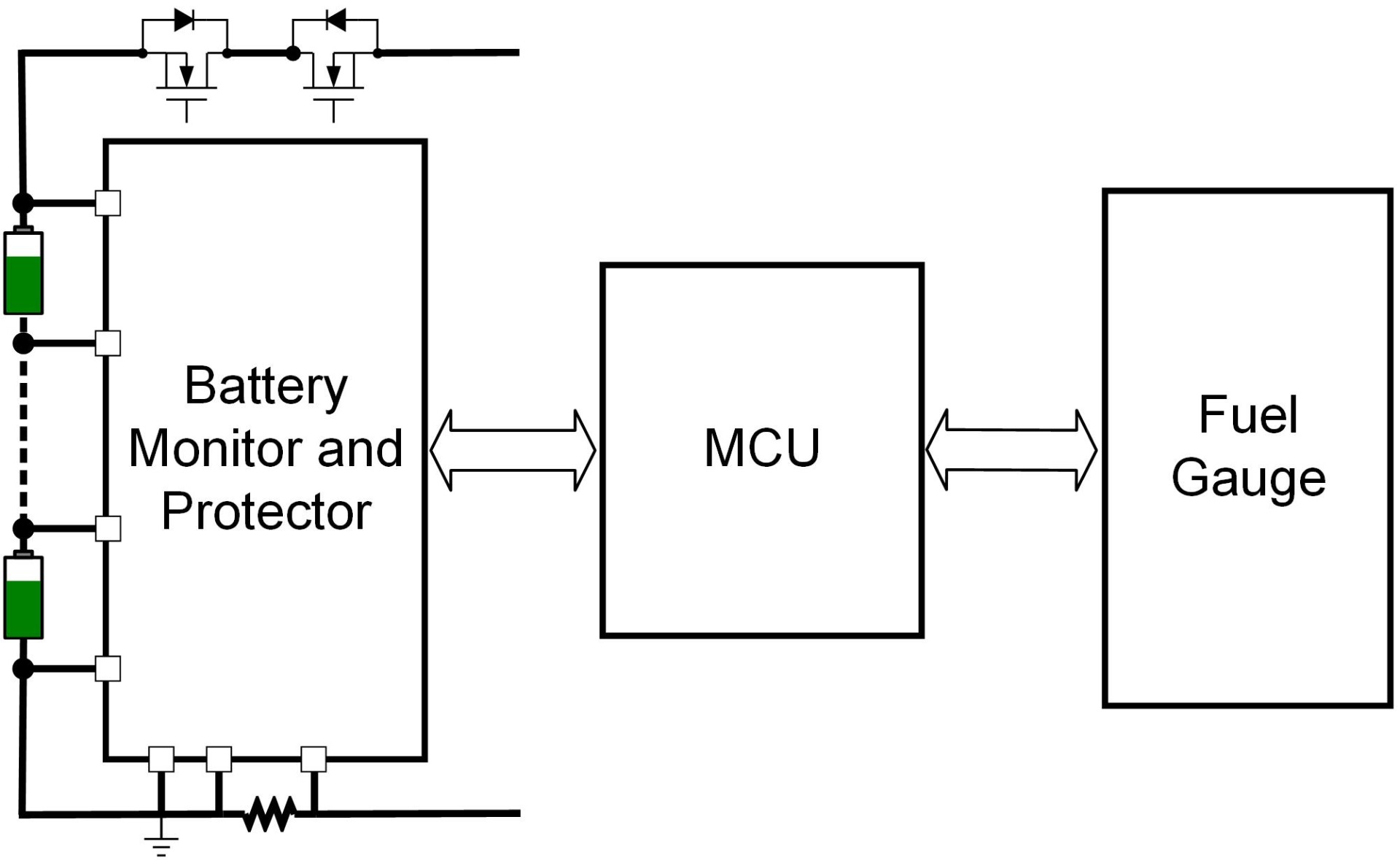
The main structure of a BMS for a low- or medium-voltage battery is commonly made up of three ICs, described below:
- Battery monitor and protector: Also known as the analog front-end (AFE), the battery monitor and protector provides the first level of protection since it is responsible for measuring the battery’s voltages, currents, and temperatures.
- Microcontroller unit (MCU): The MCU processes the data coming from the battery monitor and protector. The MCU commonly incorporates a second level of protection, including monitoring thresholds.
- Fuel gauge (FG): The fuel gauge is a separate IC that provides the state-of-charge (SOC), state-of-health (SOH), and remaining runtime estimates, as well as other user-related battery parameters.
Figure 1 shows the main structure of a complete BMS for low- or medium-voltage batteries. The fuel gauge can be a standalone IC, or it can be embedded in the MCU. The MCU is the central element of the BMS, taking information from both the AFE and fuel gauge and interfacing with the rest of the system.
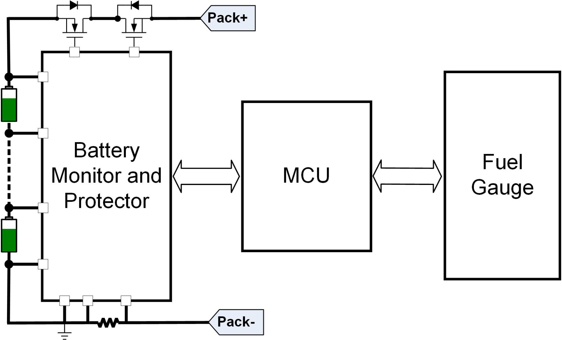
Figure 1: BMS Architecture
These three main components constitute the BMS. However, using these components without any additional consideration is not enough to ensure that the system meets the safety level required by certain industries. This article will explain the role that functional safety plays in non-automotive battery management systems and how to achieve the required safety level.
Functional Safety Introduction
Functional safety is a branch of overall safety focused on reducing the risk produced by hazardous events due to a functional failure of an electric/electronic (E/E) system. The goal is to ensure that the residual risk is within an acceptable range.
In recent years, the increasing use of E/E systems in different fields (e.g. automotive, machinery, medicine, industry, and aviation) has been accompanied by a greater emphasis on functional safety. These changes have led to the development of different functional safety standards.
ISO 13849 (titled “Safety of machinery – Safety related part of control systems”) is a functional safety standard focused on the safety-related parts of control systems (SRP/CS) in the machinery field. This is a field that includes a wide spectrum of applications, from generic industrial machinery to mopeds and e-bikes. ISO 13849 defines the different safety levels as performance level (PL), which range from PLa (lower safety level) to PLe (higher safety level). This safety standard defines an accurate process for risk evaluation and reduction. It proposes a simplified method to determine the achieved PL based on three parameters: category, mean time to dangerous failure (MTTFD), and average diagnostic coverage (DCAVG), which is calculated by averaging all the DC associated to the different safety measures applied in the system.
The category is a classification of an SRP/CS that describes its resistance to faults and the subsequent behavior in the event of a fault condition. There are 5 categories (B, 1, 2, 3, and 4).
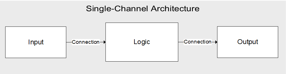
The architecture has the biggest impact on the category. The basic architecture of an SRP/CS is composed of three functional blocks: an input, a logic block, and an output (see Figure 2). Figure 2 corresponds with the architecture proposed for category B and category 1, and it is called a “single-channel” architecture. A single-channel architecture is considered the most basic architecture to implement the nominal functionality of the SRP/CS, but it is not intended for any diagnostic functionality. Category 1 and 2 rely on the reliability of their components (MTTFD) to ensure the integrity of the safety functions. If a component implementing the safety function has a failure, a safe state can no longer be guaranteed, as no diagnostics are implemented (DCAVG = 0).
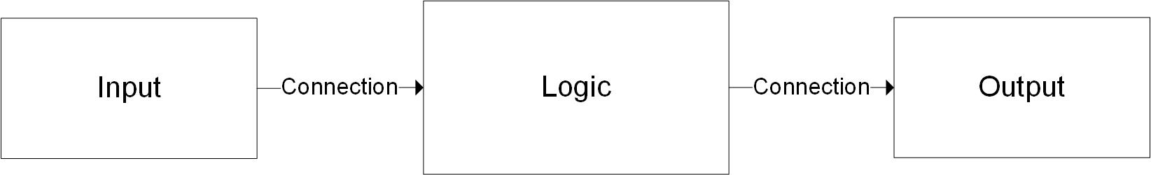
Figure 2: ISO 13849 Basic Architecture
For category 2, the proposed architecture is called “single-channel tested.” The base of this architecture is the same as the single-channel architecture, but with an added test equipment block that can diagnose whether the functional channel is working correctly. If a component implementing the safety function has a failure, the safety function is not carried out; however, a safe state can be achieved if the failure is diagnosed by the test equipment.
For category 3 and category 4, the proposed architecture is called “redundant channels,” which is implemented with two independent functional channels that can diagnose issues on the other channel. If a component implementing the safety function has a failure, the safety function can still be carried out by the other channel. Designers should select the SRP/CS category based on the targeted safety level of each safety function.


Achieving Functional Safety Step-by-Step
The ISO 13849 standard defines an iterative process during which the SRP/CS design is evaluated to determine the achieved PL and check whether that safety level is sufficient or must be improved in a new loop. The process includes three different methods for risk reduction: risk reduction via safe designs measures, risk reduction via safeguarding, and risk reduction via information for use. ISO 13849 supports risk reduction via safeguarding (see Figure 3).
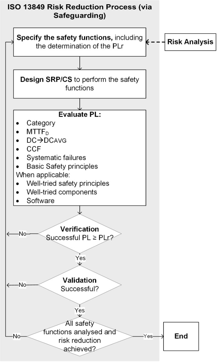
Figure 3: ISO 13849 Process (for Safeguarding)
The safeguarding process starts by defining the safety functions of the SRP/CS, in which the required performance level (PLr) is defined after the risk analysis is conducted. The PLr is the target PL of the SRP/CS for each safety function.
The next step includes designing the SRP/CS for the specified safety requirements. This entails considering the possible architecture, the safety measures to implement, and finalizing the design of the SRP/CS to perform the relevant safety functions.
Once the SRP/CS is designed, evaluate the achieved performance level for each safety function. This is the core step of the entire safeguarding process. To evaluate the achieved PL, define the category then calculate the MTTFD and DCAVG of the SRP/CS for each individual safety function.
The MTTFD is calculated per channel, and it has three levels (see Table 1).
Table 1: MTTFD Determination of Each Channel
| Denotation of Each Channel | Range of Each Channel |
| Low | 3 years ≤ MTTFD < 10 years |
| Medium | 10 years ≤ MTTFD < 30 years |
| High | 30 years ≤ MTTFD < 100 years |
Table 2 shows the four levels for defining the DC of each diagnostic measure.
Table 2: DC Determination
| Denotation | Range |
| None | DC < 60% |
| Low | 60% ≤ DC < 90% |
| Medium | 90% ≤ DC < 99% |
| High | 99% ≤ DC |
The achievable PL can be determined using the relevant parameters (see Table 3).
Table 3: How to Determine the Achievable PL
| Category | B | 1 | 2 | 2 | 3 | 3 | 4 |
| DCAVG | None | None | Low | Medium | Low | Medium | High |
| MTTFD of Each Channel | |||||||
| Low | a | Not covered | a | b | b | c | Not covered |
| Medium | b | Not covered | b | c | c | d | Not covered |
| High | Not covered | c | c | d | d | d | e |
The achievable PL can only be confirmed when the remaining requirements and analyses defined by the standard are implemented in the design. These requirements must comply with systematic failures management, CCF analysis, safety principles, and software development, if applicable.
Once this process is complete, the PL achieved by the SRP/CS for a concrete safety function should be verified against the PLr. If PL < PLr, then the SRP/CS should be redesigned and the PL evaluation process must begin again. If PL ≥ PLr, then the SRP/CS has achieved the required safety level, and validation must be executed to ensure the correct behavior through testing. If there is an unexpected behavior, the SRP/CS should be redesigned. This process should be reiterated for each safety function.
Functional Safety Level According to Each Market
Battery-powered devices are used in countless markets, and each market demands different functional safety specifications according to how dangerous a failure could be for humans and/or the environment. Table 4 shows the functional safety level required by some of the main markets. Note that these levels are constantly changing and may be different depending on each customer design.
Table 4: PL Determination Based on Market
| Electromobility | Energy Storage | Power Tools | Robotics | |
| Performance Level (PL) | PLc | PLc | PLb | PLc |
Although these are the current performance level market expectations, electromobility and certain energy storage applications may move into PLd due to the constant issues in battery-powered devices around the world. For example, faulty energy storge applications have resulted in fires in US ESS facilities. In the UK, more than 190 people have been injured and 8 people have been killed by fires sparked by faulty e-bikes and e-scooters.
All of these events could have been prevented by a more robust and reliable system. The constant need for increasing safety levels means it is vital to have a scalable solution that can be implemented across different performance levels.
MPS Functional Safety Proposal
MPS has developed an ISO 13849 BMS concept based on the implementation of the MP279x battery monitor and protectors family combined with an MCU. This system is oriented to achieve up to PLc safety level for a certain set of safety functions (SFs) (see Table 5). PLr determination is dependent on the risk analysis, in which small variations can take place, as well as the application in which the BMS is used.
Table 5: Defined Safety Functions for the BMS Concept
| SF ID | SF Description | Safe State | PLr |
| SF1 | Prevents cells from over-charging | Isolate battery from charging and discharging | PLc |
| SF2 | Prevents battery from over-charging | ||
| SF3 | Prevents cells from under-charging | ||
| SF4 | Prevents battery from under-charging | ||
| SF5 | Prevents battery from charge over-current failures | ||
| SF6 | Prevents battery from discharge over-current failures | ||
| SF7 | Prevents battery from charge short circuits | ||
| SF8 | Prevents battery from discharge short circuits | ||
| SF9 | Detects battery over-temperature | ||
| SF10 | Detects battery under-temperature |
The solution proposed by MPS to achieve PLc can meet category 2 or category 3 — depending on each safety function — as for certain safety functions, there is only a single input block and for others, there are redundant input blocks.
Figure 4 shows how to implement SF2 and SF4 (prevent the battery pack from over-charging and under-charging).
In the implementation of the SRP/CS there are two logic blocks: the battery monitor and protector (logic 1) and the MCU (logic 2). These logic blocks are used to diagnose correct functionality of different parts in the design.
The output is also duplicated by the use of the circuit braker block (output 1) and the self-controlled protector (output 2).
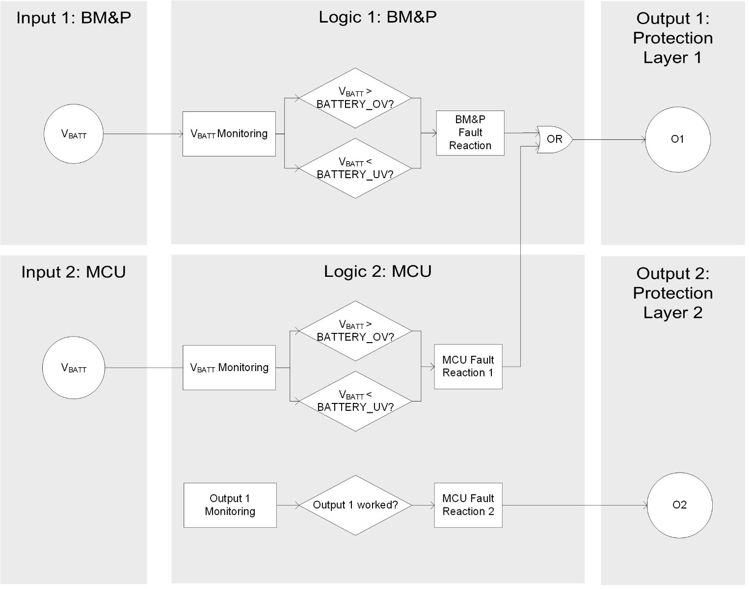
Figure 4: Implementation of SF2 and SF4
The implementation of single or duplicated input is determined by the complexity and cost in each case. To ensure that the safety functions for a single input are compliant with PLc, additional safety measures can be taken to increase the diagnostic capability; an example is a cell voltage plausibility check to verify that the cell voltage measurements are correct.
Conclusion
Functional safety used to only be relevant for to automotive products, but nowadays most modern markets demand the manufacturer to comply with a functional safety standard. The best known safety standard for non-automotive markets is ISO 13849, a system-level standard that ensures an application’s safety and robustness. MPS’s proposed architecture uses active components already included in every BMS to reduce added cost. Explore MPS’s battery monitor and protectors family family of ICs, which use this architecture and are certified as Functional Safety capable.
To learn more about how to achieve a specific performance level according to ISO 13849 using MPS devices, see the related application note.
_______________________
Did you find this interesting? Get valuable resources straight to your inbox - sent out once per month!
Technical Forum
 Latest activity 3 days ago
 5 Comments
Latest activity 3 days ago
2 Comments
Latest activity 4 days ago
14 Comments
5 Comments
Latest activity 3 days ago
2 Comments
Latest activity 4 days ago
14 Comments
Log in to your account
Create New Account