AN215 - Functional Safety Concept for BMS Solution: According to ISO 13849

Get valuable resources straight to your inbox - sent out once per month
We value your privacy
Abstract
Battery powered systems can be potentially dangerous due to their sensitivity while operating outside of the safe operating area, which could lead to a fire or an explosion. These safety risks are unacceptable for users, and therefore require specific measures to be taken to reduce the risk.
This application note describes a battery management system (BMS) architecture solution with functional safety according to ISO 13849. This application note discusses the safety functions, performance level, and definition of the safety measures implemented. These safety features reduces the risk to an acceptable level by ensuring the battery is always working within the safe operating area.
Introduction
This application note discusses the recommended safety measures to be implemented in the BMS architecture based on an MPS battery monitor and protector (BM&P) in combination with a microcontroller unit (MCU) to achieve the target performance level (PL), according to the ISO 13849 functional safety standard.
The document includes an overview of the BMS architecture, details on how to configure the BM&P, and provides the structure details for each safety measure. It also clarifies the most important points to achieve and justify the PL according to the ISO 13849 functional safety standard.
Terms and Definitions
The following terms and definitions are used throughout the application note. These terms are primarily related to functional safety, specifically in the context of the ISO 13849 functional safety standard. This section is key to understanding this application note and its purpose.
Safety Function
The safety function is the function of a machine whose failure can result in an immediate increase of risk(s).
Performance Level (PL)
The performance level (PL) is a discrete level used to specify the ability of safety-related parts of control systems (SRP/CS) to perform a safety function under specific conditions. The PL ranges from PLa (lowest) to PLe (highest) based on the SRP/CS’s ability to perform the safety function.
Required Performance Level (PLr)
The required performance level (PLr) must be met to achieve the required risk reduction for each safety function.
Dangerous Failure
A dangerous failure is the failure of an element, subsystem, and/or system that plays a part in implementing the safety function such that it:
a. Prevents a safety function from operating when required (demand mode) or causes a safety function to fail (continuous mode) such that the machine/machinery is put into hazardous or potentially hazardous state; or
b. Decreases the probability that the safety function operates correctly when required.
Mean Time to Dangerous Failure (MTTFD)
The mean time to dangerous failure (MTTFD) is the expected mean time to a dangerous failure.
Diagnostic Coverage
The diagnostic coverage is the measure of the effectiveness of diagnostics, which is determined by the ratio between the failure rate of detected dangerous failures and the failure rate of total dangerous failures.
Category
A category is the classification of the subsystem in respect to its resistance to faults and the subsequent behavior in the fault condition, which is achieved by the structural arrangement of the parts, fault detection, and/or by the subsystem’s reliability.
Architectures
The architecture is essential to determine the influence that a dangerous failure may have in the system’s ability to perform a safety function. ISO 13849 presents three pattern options, described below:
Single Channel
A single channel is composed of one input, one logic block, and one output (see Figure 1). During a dangerous failure, the safety function cannot be carried out.
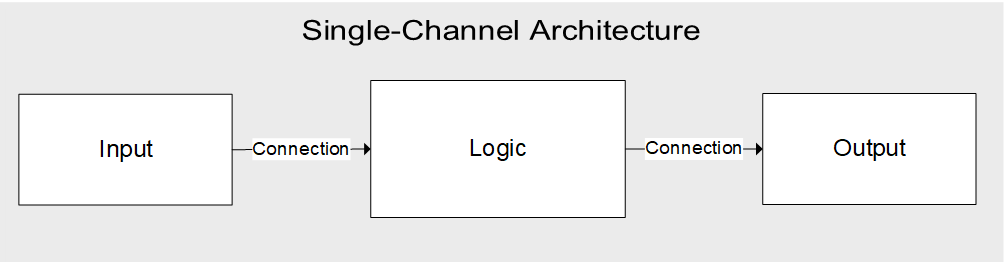
Figure 1: Single-Channel Architecture
Single-Channel Tested
A single-channel tested is similar to a single channel but includes a test of the logic block (see Figure 2). During a dangerous failure, the system can detect the failure and enter a safe state before the risk increases.
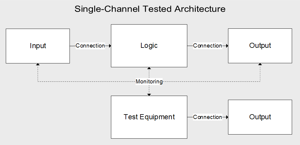
Figure 2: Single-Channel TestedArchitecture
Redundant Channels
Redundant channels are two complete channels operating in parallel (see Figure 3 on page 7). During a dangerous failure, the channel that is not experiencing the failure can still perform the safety function.
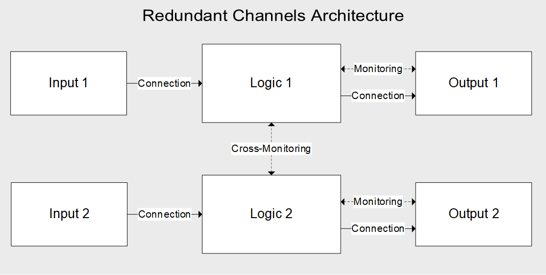
Figure 3: Redundant Channels Architecture
Categories
The ISO 13849 standard proposes a simplified method to determine the achieved PL by defining a set of five categories based on the implemented architecture, the components used (MTTFD), and the DC. These categories are listed below.
- Category B
- Architecture: Single-channel
- MTTFD: Low to medium
- DC: None
- Achievable PL: PLa to PLb
- Category 1
- Architecture: Single-channel
- MTTFD: High
- DC: None
- Achievable PL: PLa to PLc
- Category 2
- Architecture: Single-channel tested
- MTTFD: Low to high
- DC: Low to medium
- Achievable PL: PLa to PLd
- Category 3
- Architecture: Redundant channels
- MTTFD: Low to high
- DC: Low to medium
- Achievable PLM: PLb to PLd
- Category 4
- Architecture: Redundant channels
- MTTFD: High
- DC: High
- Achievable PL: PLe
- I2C and SPI communication: The safety solution is configured for I2C communication.
- General-purpose input/output (GPIO): GPIO1, GPIO2, and GPIO3.
- xALERT: Sensing interrupts from the BM&P to the MCU.
- Watchdog timer (WDT): Resets the MCU from the BM&P.
- nSHDN: Resets the BM&P from the MCU
- REGIN, VDD, and VREF: The BM&P’s internal supplies (REGIN, VDD) and internal reference voltage (VREF).
Safety Functions
The first step in the risk reduction strategy is risk analysis, where all possible scenarios of the operating conditions, failures, and potential effects are analyzed. As an outcome of this process, the safety functions and their required performance levels (PLr) are identified. Table 1 shows the typical safety functions for a battery system, including a description and PLr. In addition, the safety measures, which are described later on in the document, are traced to each of the safety functions.
Table 1: Safety Function (SF) Definitions for BMS
| SF ID | SF Description | Safe State | PLr | Safety Measures Applied |
| SF1 | Prevents cells from over-charging | Isolate battery from charging and discharging | PLc | SM2, SM5, SM6, SM7, SM8, SM9, SM11, SM12, SM13, SM14, SM15, SM16, SM17 |
| SF2 | Prevents battery from over-charging | Isolate battery from charging and discharging | PLc | SM1, SM5, SM6, SM7, SM8, SM9, SM11, SM13, SM14, SM15, SM16, SM17 |
| SF3 | Prevents cells from under-charging | Isolate battery from charging and discharging | PLc | SM2, SM5, SM6, SM7, SM8, SM9, SM11, SM12, SM13, SM14, SM15, SM16, SM17 |
| SF4 | Prevents battery from under-charging | Isolate battery from charging and discharging | PLc | SM1, SM5, SM6, SM7, SM8, SM9, SM11, SM13, SM14, SM15, SM16, SM17 |
| SF5 | Prevents battery from charge over-current (OC) failures | Isolate battery from charging and discharging | PLc | SM3, SM5, SM6, SM9, SM11, SM13, SM14, SM15, SM16, SM17 |
| SF6 | Prevents battery from discharge OC failures | Isolate battery from charging and discharging | PLc | SM3, SM5, SM6, SM9, SM11, SM13, SM14, SM15, SM16, SM17 |
| SF7 | Prevents battery from charge short circuits | Isolate battery from charging and discharging | PLc | SM3, SM9, SM11, SM13, SM17 |
| SF8 | Prevents battery from discharge short circuits | Isolate battery from charging and discharging | PLc | SM3, SM9, SM11, SM13, SM17 |
| SF9 | Detects battery over-temperature (OT) | Isolate battery from charging and discharging | PLc | SM4, SM5, SM6, SM9, SM10, SM11, SM13, SM14, SM15, SM16, SM17 |
| SF10 | Detects battery under-temperature (UT) | Isolate battery from charging and discharging | PLc | SM4, SM5, SM6, SM9, SM10, SM11, SM13, SM14, SM15, SM16, SM17 |
BMS Architecture
This section describes how the BMS architecture is used to implement the safety functions. Although a fuel gauge is typically used in a BMS, one is not shown or discussed in this document because it is not relevant to the functional safety features. Figure 4 shows the BMS system architecture.
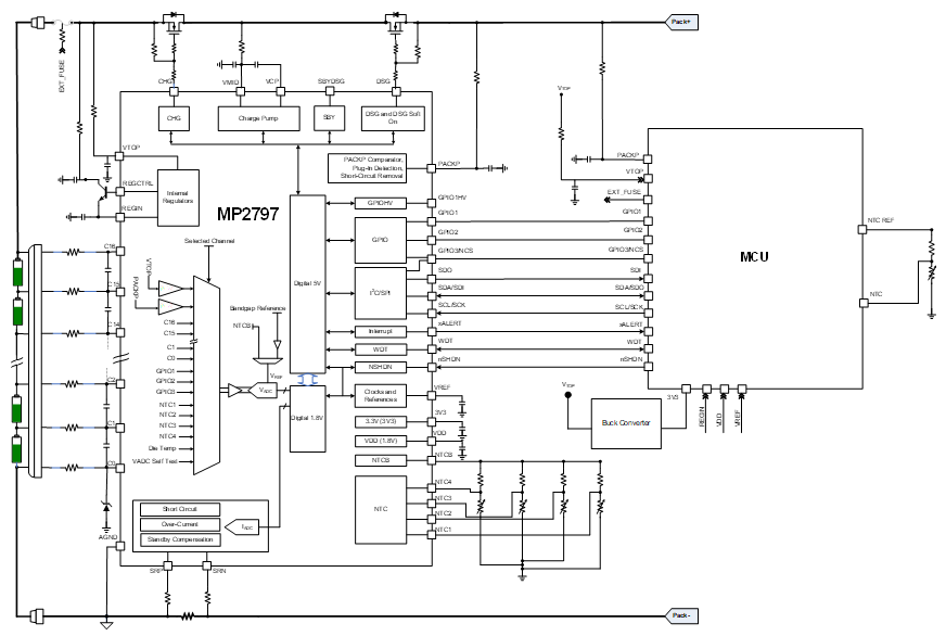
Figure 4: BMS System Architecture
The system architecture is based on an MPS BM&P (MP279x family) combined with an MCU. The BM&P senses the battery magnitudes (voltage, current, and temperature). The MCU also senses the batteryand pack voltages and battery temperature. After the sensing stage, these values can be monitored by the BM&P and the MCU. The BM&P and the MCU are connected through several interfaces, described below:
The power supply architecture implemented in this concept ensures independence from the supply point of view between the BM&P and the MCU. The BM&P is connected directly to the battery voltage through a high-voltage input pin capable of withstanding voltage values that exceed the maximum battery voltage.
This battery voltage goes internally into a voltage regulator block from which the different internal supplies are generated. The MCU is supplied with an external buck converter; the converter’s input is connected to the battery voltage, and its output is connected directly to the MCU. The only common point in the supply for both chips is the battery, which is monitored for over-voltage (OV) and under-voltage (UV) events by the analog front-end (AFE) and MCU.
Both ICs can implement protections and trigger a fault reaction to transition to the safe state. The safe state can be achieved by opening the different protection layers implemented in the power line, which can isolate the battery from charging and discharging.
The first protection layer consists of contactors or protection MOSFETs (see Figure 4 on page 10). The second protection layer consists of a self-controlled protector (SCP), which is a fuse that can be triggered both with and without an external command. The SCP is a non-resettable device, and should be configured to only be triggered if the first protection layer fails.
The mechanism to blow the SCP through its internal heater has a power dissipation operational range that must be met to ensure that the SCP is blown safely. The standard method to blow the fuse through the heater is by closing the transistor that controls the current flow through the heater, then to keep the transistor closed until the fuse blows. Due to the battery voltage level, however, this method may not ensure that the power dissipation through the heater is within the power dissipation operational range, as the power dissipation depends on the battery voltage and the heater’s internal resistor.
It is important to ensure that the power dissipation exceeds the lower threshold and is below the upper threshold. If the power dissipation is below the lower threshold, the fuse does not blow because of the heat produced in the heater. If the power dissipation exceeds the upper threshold, the heater can break before fusing the fuse.
If the standard method to blow the SCP does not ensure that the power dissipation generated in its internal heater is within its nominal range across the battery voltage’s operational range, a method to overcome this SCP limitation is by choosing an SCP that has an internal heater with a sufficiently low resistance. In this scenario, the power dissipation through the heater is within the power dissipation operational range at the minimum battery voltage level; apply a pulse-width modulation (PWM) control signal with an adjustable duty cycle so that the average power dissipation of the SCP’s internal heater is always within its power dissipation operational range.
The power dissipation operational range depends on the SCP used, so it should be addressed in each case by the system integrator. The system integrator is responsible for selecting the SCP and applying the correct control to it in order to ensure a safe and correct SCP is blown across the battery voltage’s operational range.
_______________________
Did you find this interesting? Get valuable resources straight to your inbox - sent out once per month!
Technical Forum
 Latest activity 2 days ago
 5 Comments
Latest activity 2 days ago
2 Comments
Latest activity 4 days ago
14 Comments
5 Comments
Latest activity 2 days ago
2 Comments
Latest activity 4 days ago
14 Comments
Log in to your account
Create New Account