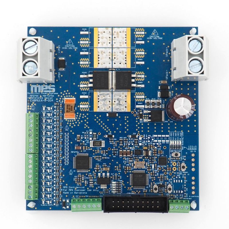
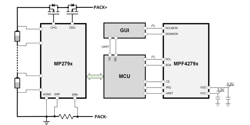
Battery Management System Solution Module

DOWNLOAD USER GUIDE
DOWNLOAD PRODUCT
BRIEF

Get valuable resources straight to your inbox - sent out once per month

Subscribe

We value your privacy

Overview

Introduction

The MBMxxS-P50-x is an evaluation kit for the BMUxxS-P50-x, a reference design board for a 7-cell to 16-cell in series battery management unit.

This board uses the MP279x ICs, a robust family of battery management analog front-ends (AFEs) that provide a complete AFE monitoring and protection solution. The MP279x supports up to 16 cells in series, and provides two separate analog-to-digital converters (ADCs) for synchronous voltage and current measurements. The high-side MOSFET (HS-FET) driver and robust HW protection functions come with configurable thresholds. Protections include over-current protection (OCP), short-circuit protection (SCP), battery and cell over-voltage protection (OVP), battery and cell under-voltage protection (UVP), over-temperature protection (OTP), and under-temperature protection (UTP). The MP279x also integrates internal balancing FETs to equalize mismatched cells while offering the option to control external FETs for a higher balancing current.

The board also features the MPF4279x, a standalone battery fuel gauge (FG) IC that performs state-of-charge (SoC), time-to-full, time-to-empty, and unavailable energy estimation using a custom battery model obtained through exhaustive characterization and voltage, current, and temperature readings. This solution is fast, simple, and easy to configure through the graphic user interface (GUI). Figure 1 shows the MBMxxS-P50-X block diagram.

Figure 1: MBMxxS-P50-x Block Diagram Design

Each MBMxxS-P50-x evaluation board offers a different combination of the MP279x AFE and the MPF4279x fuel gauge. See the Evaluation Kits section on page 5 for more details.

Evaluation Kits

Reference Design MPF4279x Part Number MPF4279x Short Description MP279x Part Number MP279x Short Description
MBM16S-P50 MPF42790 2-Cell to 16-Cell FG with Level LEDs MP2797 7-Cell to 16-Cell BMS with I2C
MBM14S-P50 MPF42790 2-Cell to 14-Cell FG with Level LEDs MP2791 7-Cell to 14-Cell BMS with I2C
MBM10S-P50 MPF42795 2-Cell to 10-Cell FG with Level LEDs MP2791 7-Cell to 14-Cell BMS with I2C
MBM16S-P50-B MPF42791 Next Generation 2-Cell to 16-Cell FG with Level LEDs MP2797 7-Cell to 16-Cell BMS with I2C
MBM14S-P50-B MPF42791 Next Generation 2-Cell to 14-Cell FG with Level LEDs MP2791 7-Cell to 14-Cell BMS with I2C


Kit Contents

MBM16S-P50

Items included with the kit (items below can be ordered separately):

# Part Number Item Quantity
1 BMU16S-P50-R01A MP2797DFP-0001-T and MPF42790DRT-0B-0001 or MPF42792DRT-0B-0001 reference design and evaluation board 1
2 EVKT-USB_RS232/I2C-01 USB to RS232 / I2C adapter 1

MBM14S-P50

Items included with the kit (items below can be ordered separately):

# Part Number Item Quantity
1 BMU14S-P50-R01A MP2791DFP-0001-T and MPF42790DRT-0B-0001 or reference design and evaluation board 1
2 EVKT-USB_RS232/I2C-01 USB to RS232 / I2C adapter 1

MBM10S-P50

Items included with the kit (items below can be ordered separately):

# Part Number Item Quantity
1 BMU10S-P50-R01A MP2791DFP-0001-T and MPF42795DRT-0B-0001 or MPF42797DRT-0B-0001 reference design and evaluation board 1
2 EVKT-USB_RS232/I2C-01 USB to RS232 / I2C adapter 1

MBM16S-P50-B

Items included with the kit (items below can be ordered separately):

# Part Number Item Quantity
1 BMU16S-P50-B-R01A MP2797DFP-0001-T and MPF42791DRT-0B-0001 reference design and evaluation board 1
2 EVKT-USB_RS232/I2C-01 USB to RS232 / I2C adapter 1

MBM14S-P50-B

Items included with the kit (items below can be ordered separately):

# Part Number Item Quantity
1 BMU14S-P50B-R01A MP2791DFP-0001-T and MPF42791DRT-0B-0001 reference design and evaluation board 1
2 EVKT-USB_RS232/I2C-01 USB to RS232 / I2C adapter 1

Figure 2: MBMxxS-P50-x Evaluation Kit Set-Up

Features and Benefits

  • High-Side Charge and Discharge (Including Pre-Charge Function) MOSFETs
  • 7 Cells, Up to 16 Cells in Series
  • True Hardware Protections
  • High-Accuracy ADC with the Option of Simultaneous Voltage and Current Measurements
  • Configurable Alarm Reactions and Thresholds
    • Configurable Over-Voltage Protection (OVP) and Under-Voltage Protection (UVP)
    • Configurable Charge and Discharge Over-Current Protection (OCP) and Short-Circuit Protection (SCP)
    • Configurable PCB and Battery Over-Temperature Protection (OTP)
    • Self-Functionality Test Options
  • Cell-Balancing with Internal MP279x FETs with Option of External FET Balancing for Higher Current
  • Open-Wire Detection
  • Sleep Mode with Standby Discharge FET for Lower Current Consumption with Automatic Wake-Up when a Load/Charger Is Detected
  • Load/Charger Detection Option in Safe Mode
  • Accurate Battery Pack State-Of-Charge (SoC) Estimation (see Figure 3)
  • Simple Configurations through MPS’s GUI
  • Supports any Lithium-Based Cell Type Using a Dedicated Battery Cell Model

Figure 3: MBM16S-P50 Performance Example

Kit Specifications (1)

Features Specifications
Max series cell support MBM16-P50-x: 16 cells in series
MBM14-P50-x: 14 cells in series
MBM10-P50-x: 10 cells in series
Battery pack voltage range MBM16-P50-x: 18V to 70.4V
MBM14-P50-x: 18V to 65.8V
MBM10-P50-x: 18V to 44V
Cell voltage range Up to 4.5V (configurable cell UV and OV thresholds)
Charge current range 0A to 130.07A (configurable charge OC threshold) (1)
Discharge current range 0A to 130.07A (configurable discharge OC threshold) (1)
Total high-side protection resistance (connectors + PCB traces + 1 parallel FETs) 4mΩ to 5mΩ
Operating systems supported Windows 7 or later
System requirements Minimum 350MB free
EVB size (LxW) 9.65cm x 9.74cm

1) It is not recommended to exceed 50A of continuous current for the 4 parallel FET configuration. However, higher peak currents are supported.


Hardware Limitations affecting Testing and Usage

The MBMxxS-P50-x family is for demonstrating only, and should never be used in a production environment

MBM16S-P50-x Limitations

The MBM16S-P50-x uses an engineering sample of the MP2797. The microcontroller (MCU) and GUI are designed to provide a simplified experience to overcome some of the sample limitations. The user should review the MP2797 datasheet and related application note to be aware of such limitations. Contact and MPS FAE for the application note.

To ensure a robust set-up, excellent performance, and optimal BOM, note the changes related to the MP2797’s engineering pre-sample. Changes that deviate from what is suggested in this guide are not advised; before doing so, contact an MPS FAE.

MBM10S-P50-x and MPM14S-P50-x Limitations

The MBM10S-P50-x and MBM14-P50-x use an engineering sample of the MP2791. The microcontroller (MCU) and GUI are designed to provide a simplified experience to overcome some of the sample limitations. The user should review the MP2791 datasheet and related application note to be aware of such limitations. Contact and MPS FAE for the application note.

To ensure a robust set-up, excellent performance, and optimal BOM, note the changes related to the MP2791’s engineering pre-sample. Changes that deviate from what is suggested in this guide are not advised; before doing so, contact an MPS FAE.