Introducing a Fully Integrated Automotive USB Type-A and USB Type-C Charger Controller

Get valuable resources straight to your inbox - sent out once per month
We value your privacy
Introduction
The car’s central control system has a USB charging port that must be able to charge mobile devices while transmitting data. For these systems, it is vital to select an automotive-grade IC with a USB current-limit switch. The article will introduce the MPQ4228-C-AEC1 and how its high efficiency can be utilized in USB hubs and other USB Type-C applications, as well as USB Type-A applications.
The MPQ4228-C-AEC1
The MPQ4228-C-AEC1 is a USB charging solution that integrates a step-down switch-mode converter with a USB current-limit switch (see Figure 1). The device supports BC1.2 charging downstream port (CDP) mode and USB Type-C 5V @ 3A downstream facing port (DFP) mode, and is available in a small QFN-22 (4mmx4mm) package. The MPQ4228-C-AEC1 integrates a synchronous DC/DC buck converter and a charger port controller that supports CDP, which can improve EMI performance and reduce PCB size by requiring fewer components.

Figure 1: MPQ4228-C-AEC1 Typical Application Circuit
The MPQ4228-C-AEC1 provides robust protections, including current-limit protection with hiccup mode (supports MFI OCP), output over-voltage protection (OVP), USB_OUT/DP/DM/CC1/CC2 to battery short protection, and over-temperature protection (OTP).
In addition, the MPQ4228-C-AEC1 can be used in USB Type-A and USB Type-C applications. The CC2 pin detects connections to configure the interface across USB Type-C cables and connectors. If the CC1 pin is connected to ground, the MPQ4228-C-AEC1 works in USB Type-A mode, and the current limit changes to the USB Type-A specifications.
Related Content
-
VIDEO
Automotive USB Charging Step-Down Converter: MPQ4228
All-in-one USB Type-C automotive charging port solutions
-
APPLICATION
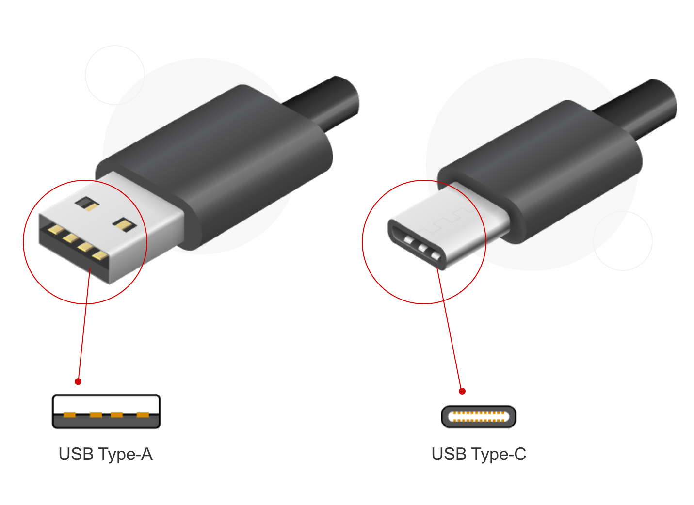
Standard USB Type-C/Type-A
MPS’s cost-effective, reliable power management solutions provide everything you need to drive the next generation of standard USB Type-C and Type-A designs
-
ARTICLE

Power Supply Design for Car Infotainment Systems (Part II)
This article addresses challenges regarding camera power supplies and USB charging in car infotainment systems
-
WEBINAR

EMC Insights and Solutions: Practical and Early Showcases
Learn how practical, early testing helps avoid issues later in the process
Efficiency
The MPQ4428-C-AEC1 features a highly efficient DC/DC converter, with a peak efficiency as high as 94.4% when the total load temperature rise is only 31°C. Because this device has a considerably high efficiency, is generates very little heat, which reduces the need for heat dissipation and can make the overall solution smaller. Figure 2 shows the efficiency curve.
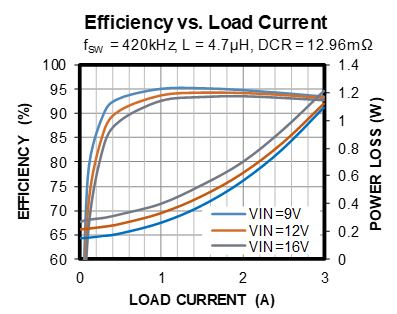
Figure 2: Efficiency vs. Load Current
Case Temperature Test
Figure 3 shows a case temperature test for the MPQ4228-C-AEC1. For this test, the input voltage (VIN) = 12V, USB = 5V, and the output current (IOUT) = 3A. Measurements were taken on a 4-layer PCB, (57.4mmx57.4mm); the top and bottom layers are 2oz, while mid-layer 1 and mid-layer 2 are 1oz. The ambient temperature (TA) is 25°C.
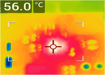
Figure 3: Case Temperature Test
Data Transmission
Data transmission requires excellent signal integrity, and the eye diagram is a test that evaluates USB 2.0 signal integrity. When the host data passes through the MPQ4228-C-AEC1’s internal DP/DM data switch, the 150cm cable has excellent eye diagram performance (see Figure 4). For this test, VIN = 12V, and the switching frequency (fSW) = 420kHz.
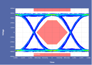
Figure 4: Eye Diagram
Electromagnetic Intererence (EMI)
As automotive electronics continuously improve, the requirements for the vehicle’s electromagnetic compatibility (EMC) performance are becoming more stringent, and electromagnetic interference (EMI) reduces device performance. Certain applications may also have more noticeable repercussions, such as noise generated by a radio.
The MPQ4228-C-AEC1’s spectrum spread function can pass the CISPR25 Class 5 standard without shielding and common-mode inductance. Figure 5 shows its conducted EMI results. This test was conducted under the following conditions: VIN = 12V, bus voltage (VBUS) = 5V, IOUT = 3A, inductance (L) = 4.7µH, fSW = 420kHz, the FREQ pin is connected to GND, and the device operates in forced pulse-width modulation (PWM) mode.
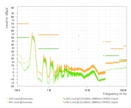
Figure 5: Conducted EMI Results
Figure 6 shows the radiated EMI results. This test was conducted under the same conditions as the conducted EMI.
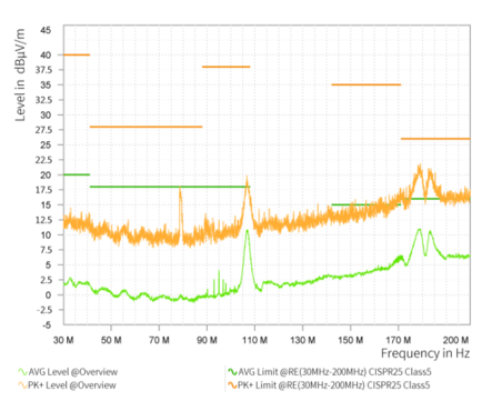
Figure 6: Radiated EMI Results
Line Drop Compensation
There is a certain distance between the car and the USB port. The line voltage drop across this distance affects the terminal’s charging voltage and charging speed. Different car models have different distances from the USB port. Therefore, the MPQ4228-C-AEC1 defines the line loss compensation, which can be flexibly configured.
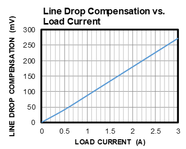
Figure 7: Line Drop Compensation vs. Load Current
The MPQ4228-C-AEC1 is part of the MPQ4228 family, which includes the following parts:
- The MPQ4228-AEC1, which supports Apple 3A Divider mode and DCP schemes for BC1.2 and 1.2V/1.2V mode.
- The MPQ4228-Q-AEC1, which supports Quick Charge (QC3.0) mode and is backward compatible with DCP schemes for BC1.2, Apple 3A divider mode, and 1.2V/1.2V mode.
The MPQ4228 family can pass the ±8kV IEC 61000-4-2 contact discharge test and ±15kV IEC 61000-4-2 air discharge test with battery short protection for the VBUS/DM/DP/CC pins.
Conclusion
This article described the benefits of using the MPQ4228-C-AEC1, such as high efficiency, excellent EMI performance, and optimized heat dissipation. In addition to the MPQ4228-C-AEC1, there is a video introducing the MPQ4228-AEC1, which is part of the MPQ4228 family. MPS offers a robust array of AECQ-100 qualified USB charging ports that can meet any design’s needs.
_______________________
Did you find this interesting? Get valuable resources straight to your inbox - sent out once per month!
Technical Forum
 Latest activity 24 hours ago
 1 Comment
Latest activity 2 weeks ago
3 Comments
Latest activity 3 weeks ago
2 Comments
1 Comment
Latest activity 2 weeks ago
3 Comments
Latest activity 3 weeks ago
2 Comments
Log in to your account
Create New Account