


The Theory of Parasitic Miller Turn-On and Driving Techniques for SiC MOSFETs and Cascodes
DOWNLOAD PDF


Get valuable resources straight to your inbox - sent out once per month
We value your privacy
Introduction
To address the constant challenges that accompany increasing a power converter’s power density, switching frequency (fSW), and efficiency, it is vital that designers can switch power transistors quickly and safely. These needs have made wide-bandgap power semiconductors like silicon carbide (SiC) MOSFETs and cascodes more popular than silicon counterparts; however, these devices also work at much higher voltage slopes (dV/dt), which require special attention to avoid inducing a Miller turn-on.
If MOSFETs experience an unexpected turn-on due to the Miller capacitance, the bridge structures on the power converters may briefly enter shoot-through, which can lead to harmful effects ranging from a slight increase in temperature to the destruction of the device. Avoiding this effect often leads to overengineered gate driver designs, which result in suboptimal, slow, and more expensive circuits.
This article describes the induced turn-on effect on power MOSFETs and cascodes due to the Miller parasitic capacity. It will discuss the elements that influence this effect, the driving configurations that can prevent issues caused by this phenomenon, and how cascodes have an advantageous structure that minimizes the risks related to Miller capacitance while eliminating the need for additional elements (e.g. gate driver, gate-source capacitor).
The Miller Effect
Named after its discoverer, the Miller effect can be generalized for any inverting amplifier voltage circuit. The Miller effect states that any circuit working as an inverting voltage amplifier will experience an increase in the equivalent input capacitance due to the capacitive path between the input and output (reverse transfer capacitance). The higher the amplifier’s gain, the higher the increase.
High-voltage MOSFET transistors and cascodes are a particular case of high-gain, inverting voltage amplifiers, and the equivalent parasitic capacitance between the gate and drain (CGD) works as a reverse transfer capacitance.
Figure 1 shows how the cascode configuration stacks the parasitic capacitances in series, resulting in a lower equivalent reverse transfer capacitance that minimizes the Miller effect. In the active control path — when the gate-to-source (VGS) voltage actively controls the drain-to-source voltage (VDS) — this phenomenon is the Miller effect, which limits the effective bandwidth (switching speed) of the transistors since most of the charge coming from the gate is derived to the transfer capacitance while VDS rises/falls suddenly.
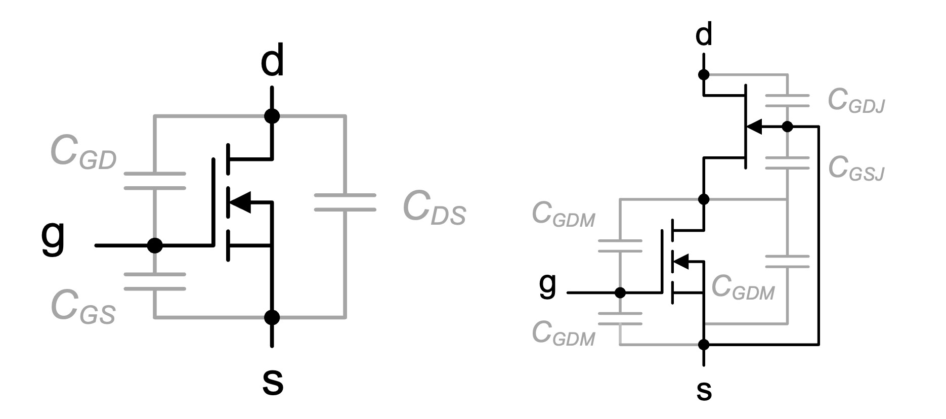
Figure 1: Parasitic Capacitances on SiC MOSFET (Left) and SiC Cascode (Right)
In the opposite direction, when the power FET works as a passive diode, the FET may experience a sudden slope on the drain-to-source terminals (e.g. the diode is forward polarized). In this scenario, the reverse transfer capacity provides a path to charge the gate-to-source capacitance (CGS). If CGS is not checked, this may induce an undesired turn-on, which is explained below in greater detail.
Induced Turn-On Due to the Miller Effect
Half-bridge topologies are a very common configuration for power converters that may suffer from the Miller effect. The process is explained below.
- When the high-side MOSFET (HS-FET) turns on, its drain-to-source voltage (VDS(HS)) drops (negative VDS(HS) slope) to practically 0V.
- The drop in VDS(HS) causes the low-side MOSFET’s (LS-FET, which is acting as a diode) drain-to-source voltage (VDS(LS)) to increase with the same slope, albeit positively.
- The LS-FET’s slope (dVDS(LS)/dt) causes the gate-to-drain capacity to charge (Miller effect), which generates a current displacement (ICGD). This is also called the Miller current.
- Most of the Miller current that is not drawn by the gate circuitry goes towards charging the input capacitance (CGS), thereby increasing the LS-FET’s gate-to-source voltage (VGS(LS)).
Figure 2 shows SiC MOSFETs in a half-bridge configuration driven by the MP18831 gate driver. In this figure, the Miller current’s path is highlighted in blue.
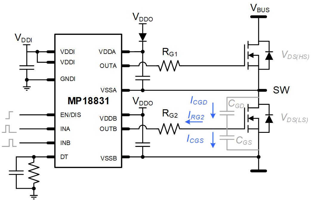
Figure 2: SiC MOSFETs in a Half-Bridge Configuration
Figure 3 shows this entire process. If ΔVGS(LS) exceeds the threshold voltage (VTH), then the LS-FET enters conduction for as long as gate voltage remains over the threshold, which causes shoot-through. The same is true for the opposing scenario, in which the LS-FET actively triggers and induces an undesired HS-FET turn-on.
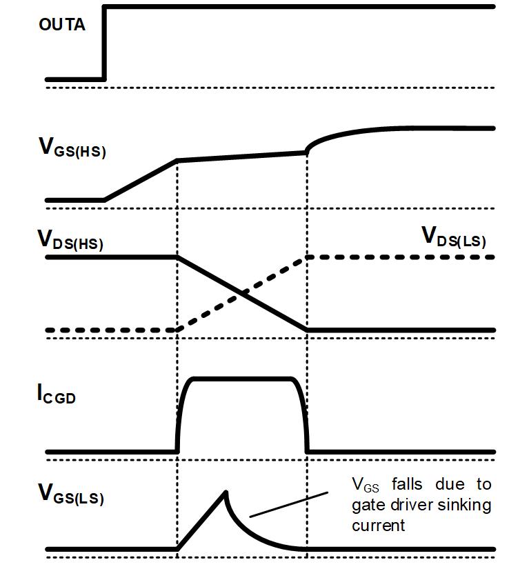
Figure 3: Current and Voltage Waveforms
Now it is time to quantify the phenomenon to determine the likelihood that it could happen in our design. By applying Kirchhoff’s current law (KCL) on the LS-FET’s gate node, we can calculate the Miller current (denoted as ICGD in Figure 2) with Equation (1):
ICGD = ICGS + IRG2 (1)
Equation (1) can be expanded to Equation (2):
CGD × dVDGdt = CGS × dVGSdt + IRG2 (2)
Note that for high-voltage systems (VBUS >> VGS) we can approximate VDG to be about equal to VDS. Non-idealities such as gate loop inductance, internal FET gate resistance, or the gate driver IC’s saturation current modify the gate driver’s effective sink current (IRG2), which makes it difficult to determine how the gate driver contributes to ICGD.
For simplicity, we can assume that if the gate driver is unable to sink any current fast enough to prevent CGS from being charged (which occurs when IRG2 ≈ 0A), then the voltage rise on the gate is the result of a capacitive voltage divider. The change in VGS can be calculated with Equation (3):
ΔVGS = CGDCGS × ΔVDS (3)
If the resulting ΔVGS does not cause the gate voltage to exceed the threshold voltage, this means that we do not need to rely on components besides the MOSFET to discharge the gate. Since CGD is not a constant value and varies among VDS, using charges is more reliable. Equation (4) is derived from Equation (3). Equation (4) is an alternative equation that indicates the odds of surpassing the threshold voltage in relation to the charge balance:
QGD(VDS)QGS(TH)(VSSO) (4)
Equation (4), also known as the Miller ratio, establishes a relationship between the charge displaced on CGD due to an increase of VDS, and the charge required by CGS to reach VTH (from the turn-off voltage rail, VSSO). Similarly, if the ratio is below 1, additional elements are not needed for safety. This method is often more convenient than Equation (3) because values can be easily extracted from the MOSFET’s datasheet parameters. This formula is just an approximation; because the gate driver tries to keep the device off, it is necessary to consider how the gate driver’s charge sink impacts the ratio.
Obtaining the Miller Ratio from Datasheet Parameters
The gate charges that are indicated on the electrical characteristics chart are discrete (see Table 1). Note that these values are specific to the conditions listed below.
Table 1: Gate Charge Parameters in a SiC Cascode Datasheet
| Parameter | Symbol | Conditions | Min | Typ | Max | Units |
|---|---|---|---|---|---|---|
| Threshold gate-to-source charge | QGS(TH) | VDS = 400V, ID = 50A, VGS = 0V to 12V |
14 | nC | ||
| Plateau gate-to-source charge | QGS(PL) | 26 | nC | |||
| Gate-to-drain charge | QGD | 6 | nC | |||
| Total gate charge | QG | 50 | nC |


The test conditions are set to be realistic with the final application (e.g. the usual bus voltages and recommended driving rails). A quick inspection of the chart values gives us an idea of the chosen transistor’s Miller ratio. If the final application differs from the test conditions, we can check for the typical gate charge curve and linearly extrapolate the values for different voltage rails (see Figure 4).
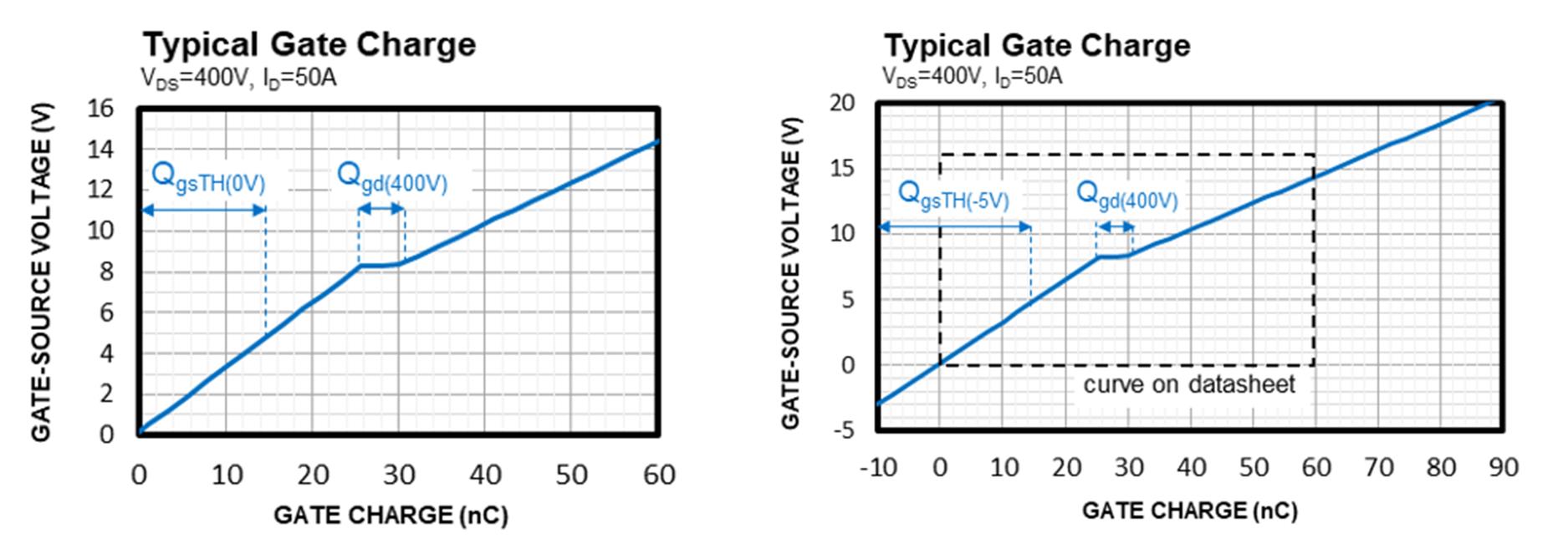
Figure 4: Gate Charge Curve from the Datasheet (Left) and the Extended Axis Values (Right)
Mitigation Techniques
A few methods to reduce the Miller turn-on and enhance the FET from the driving perspective are described below.
Pick a Discrete Device with a Favorable Miller Ratio
Picking a FET with an optimal Miller ratio is the most obvious method to reduce the turn-on effect, as it eliminates the need for overengineering. As explained above, once a designer knows the maximum drain-to-source voltage at which the switch operates, designers should calculate the worst-case QGD/QGS for the driving conditions. If the calculated value is below 1, then the device is safe.
Increase the Gate-to-Source Capacitance (CGS)
This is a simple troubleshooting method. Any capacitor placed between the gate and the source pins of the power FET are added to the internal CGS, which improves the Miller ratio. The tradeoff is that boosting this capacitance also increase the gate driver’s power consumption, and the equivalent gate capacitance to be charged/discharged on each cycle also increases.
Use a Lower Ohmic Value Turn-Off Gate Resistor (RGOFF)
By using a turn-off gate resistor (RGOFF) with a low ohmic value, we can push the gate driver to sink the gate charge more quickly when the Miller current appears. This prevents CGS from being charged excessively, and does not increase the gate driver’s power consumption. If this is the approach is used, also consider a good layout design with reduced gate loop inductance; otherwise, the driver circuit may not be able to evacuate the charges fast enough (see Figure 5). In addition, this solution comes with a tradeoff: Imposing a low-value RGOFF also sets a higher turn-off slope and may create other EMI issues.
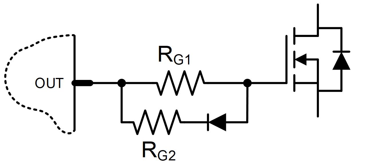
Figure 5: Typical Configuration to Obtain Lower RGOFF than RGON on Single-Output Gate Drivers
Use (or Increase) the Negative Rail
Setting a negative voltage at which the transistor turns off (VSSO), or increasing the negative voltage if it is already in place, is an alternative way of extending QGS(TH) (see Figure 4). The main concern for the designer is how to add a negative supply rail for the gate driver’s circuitry. When using a negative rail, a classic bootstrap technique for the high-side driver supply does not work. This may be an inconvenience to compact or low-cost designs.
Active Miller Clamp
To avoid shoot-through without jeopardizing the controllability of the gate, we can use Miller Clamp circuitry. Some monolithic gate driver ICs, such as the MPQ18811, implement this feature (see Figure 6). In this figure, the clamp discharge path is highlighted in blue.
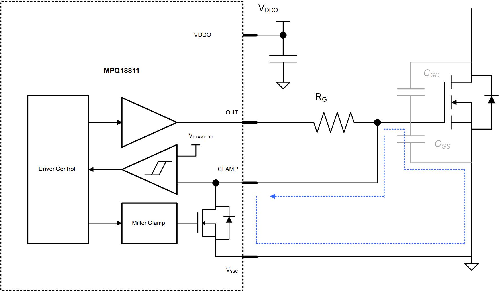
Figure 6: Active Miller Clamp Diagram in the MPQ18811 with Clamp Discharge Path
The Miller clamp operates in the following manner: shortly after the device has been turned off (VGS almost reaches VSSO) the driver activates the circuitry to clamp the gate, creating a very low-impedance path between the gate and VSSO (see Figure 7). This path has to be minimized in the layout for optimal results. Because the clamp circuit is an alternate path for the gate loop, it can independently turn our device on and off with the preferred gate resistances and driver rails.
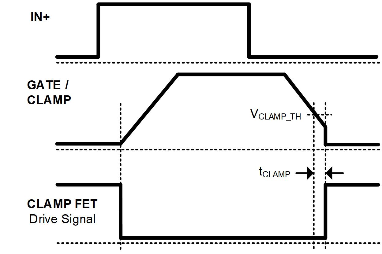
Figure 7: Operation Chronogram
Conclusion
This article explained the induced turn-on due to the Miller effect on SiC MOSFETs and SiC cascodes. This article also discussed several techniques to prevent the induced turn-on for power FETs with a high Miller ratio.
First, the Miller ratio is a good indicator when trying to determine a power FET’s immunity against this phenomenon. Second, the internal structure on silicon carbide cascodes exhibits a reduced reverse transfer capacitance, which improves robustness against the induced turn-on (in relation to its SiC MOSFET counterparts).
Lastly, gate driver ICs such as the MPQ18811 include a Miller clamp, which is a peripheral specifically designed to address this issue independently of the FET’s internal parameters or gate driver conditions. A Miller clamp allows the designer to drive any type of power FET without worrying about parasitic Miller turn-on.
In addition to the MPQ18811, MPS offers other automotive-grade gate drivers to suit a variety of applications.
_______________________
Did you find this interesting? Get valuable resources straight to your inbox - sent out once per month!
Technical Forum
 Latest activity 3 months ago
 4 Comments
Latest activity 3 months ago
1 Comment
Latest activity 4 days ago
4 Comments
Log in to your account
Create New Account