Active Balancing: How It Works and Its Advantages

Get valuable resources straight to your inbox - sent out once per month
We value your privacy
Introduction
The stability and safety of lithium batteries requires treating them with careful consideration. If lithium-ion battery cells do not operate within a constrained state-of-charge (SOC) range, their capacity can be reduced. If they are pushed beyond their SOC limits, these batteries can be damaged, leading to unstable and unsafe behavior. To ensure the safety, lifetime, and capacity of lithium-ion battery cells, their SOC must be carefully limited.
To maximize each battery cell’s useful capacity and life, degradation must be minimized while operating all cells across a full SOC range. Simply keeping cells within a constrained SOC without intervention will avoid degradation but slowly decrease the usable capacity by the amount of SOC mismatch. That is because charging or discharging must stop when one cell reaches the upper or lower SOC limit, even though the other cells have remaining capacity (see Figure 1).

Figure 1: The Useful Capacity of a Battery Pack Is Decreased by the Mismatched SOC
Most battery management systems (BMS) today include passive balancing to periodically bring all cells in series to a common SOC value. Passive balancing does this by connecting a resistor across each individual cell as necessary to dissipate energy and lower the SOC of the cell. As an alternative to passive balancing, active balancing uses power conversion to redistribute charge among the cells in a battery pack. This allows for a higher balancing current, lower heat generation, faster balancing time, higher energy efficiency, and longer operating range.
This article describes a few common active balancing methods and provides a design example using one of these methods.
Cell Balancing
Cells in a pack develop capacity variation over time, even if they are initially well-matched. For example, cells at different physical locations in a pack can experience different temperatures or pressures that effect capacity. In addition, slight manufacturing differences can be amplified over time and create differences in capacity. Understanding capacity differences is critical to understanding the source of SOC imbalance.
Changes in battery cell SOC are primarily dictated by cell capacity and the current in, or out of, a cell. For example, a 4Ahr cell receiving 1A for 1hr will experience a 25% SOC change, while a similar 2Ahr cell will experience a 50% SOC change.
Maintaining SOC balance requires adjusting each cell’s charge/discharge current according to its capacity. Cells that are connected in parallel automatically do this, since current will flow from high-SOC cells to low-SOC cells. In contrast, cells in series experience the same current between cells, which creates an imbalance if there are capacity differences. This is important since most battery packs have series cell connections, even if they also include parallel connections.
SOC adjustment is possible for both passive and active balancing.
Passive balancing reduces cell SOC by placing a resistive load across individual cells (most commonly using BJT or MOSFET transistors). But active balancing takes a switch-mode approach to redistribute energy between cells in a battery pack. The added complexity and cost of implementation has traditionally limited active balancing to battery systems with very higher power levels and/or large capacity cells, such as batteries in power stations, commercial energy storage systems (ESS), home ESS, and battery backup units. New solutions are now available with significantly lower cost and complexity, enabling a growing range of applications to leverage the advantages of active balancing.
Passive balancing is typically limited to 0.25A of current, while active balancing can support up to 6A. A higher balancing current allows for faster balancing, which supports larger-capacity battery cells, such as those used in ESS. In addition, a higher balancing current supports systems operating on fast cycles where balancing must be completed quickly.
Passive balancing simply dissipates energy; active balancing, however, redistributes energy with a significant improvement in energy efficiency. Passive balancing is only practical during the charge cycle, since operation during discharge hastens energy depletion from the pack. Conversely, active balancing can be implemented during charging or discharging. The ability to actively balance during discharge provides more balancing time and allows charge to be transferred from the strong cells to the weak cells, thereby extending battery pack runtime (see Figure 2). In summary, active balancing is advantageous for applications that require faster balancing, limited thermal load, improved energy efficiency, and increased system runtime.
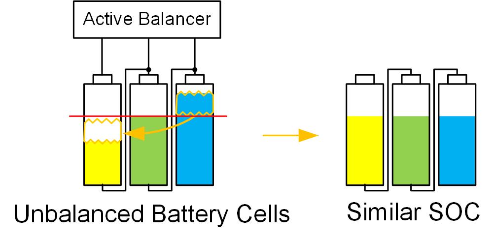
Figure 2: Active Balancer Equalizes the SOC
Active Balancing Methods
Commonly used active balancing topologies include direct transformer-based, switch matrix plus transformer, and bidirectional buck-boost balancing.
Transformer-Based (Bidirectional Flyback) Active Balancer
A bidirectional flyback converter allows charge to be transferred in both directions. The bidirectional flyback is designed to operate as a boundary mode flyback converter. Each battery cell in the stack requires a bidirectional flyback, including a flyback transformer (see Figure 3).
Figure 3: A Transformer-Based Bidirectional Active Balancer Using a 24V Rail
When using different transformer designs, there are several possible energy transfer paths. For example, energy can be transferred from one cell to a sub-group of cells within the battery stack. Energy can be transferred from any cell to the top of the battery stack (connected to the battery pack terminals), which requires a large, high-voltage flyback transformer. Energy can also be transferred to or from an auxiliary power rail, such as a 24V system (see Figure 3).
Many transformers are often required when using the transformer-based active balancing approach, which results in large, costly solutions for battery packs with a high string count.
Switch Matrix plus Transformer Active Balancer
The switch matrix plus transformer method uses an array of switches to connect a transformer to and from individual cells; this reduces the number of transformers to one. Within a switch matrix, there are two categories of switches: cell switches and polarity switches. The cell switches are back-to-back MOSFETs connected directly to the battery cells. They can block the current flowing in both charge and discharge directions. Conversely, the polarity switches block the current flowing in one direction only, and they are connected directly to the secondary side of a single, bidirectional flyback converter or a bidirectional forward converter (see Figure 4).
The primary side of the bidirectional flyback converter or the forward converter is connected to the battery pack or an auxiliary power rail. In this arrangement, every cell can exchange the energy (during charge or discharge) with the battery pack or an auxiliary power rail. As noted, the primary advantage of the switch matrix plus transformer is that only one transformer is required.
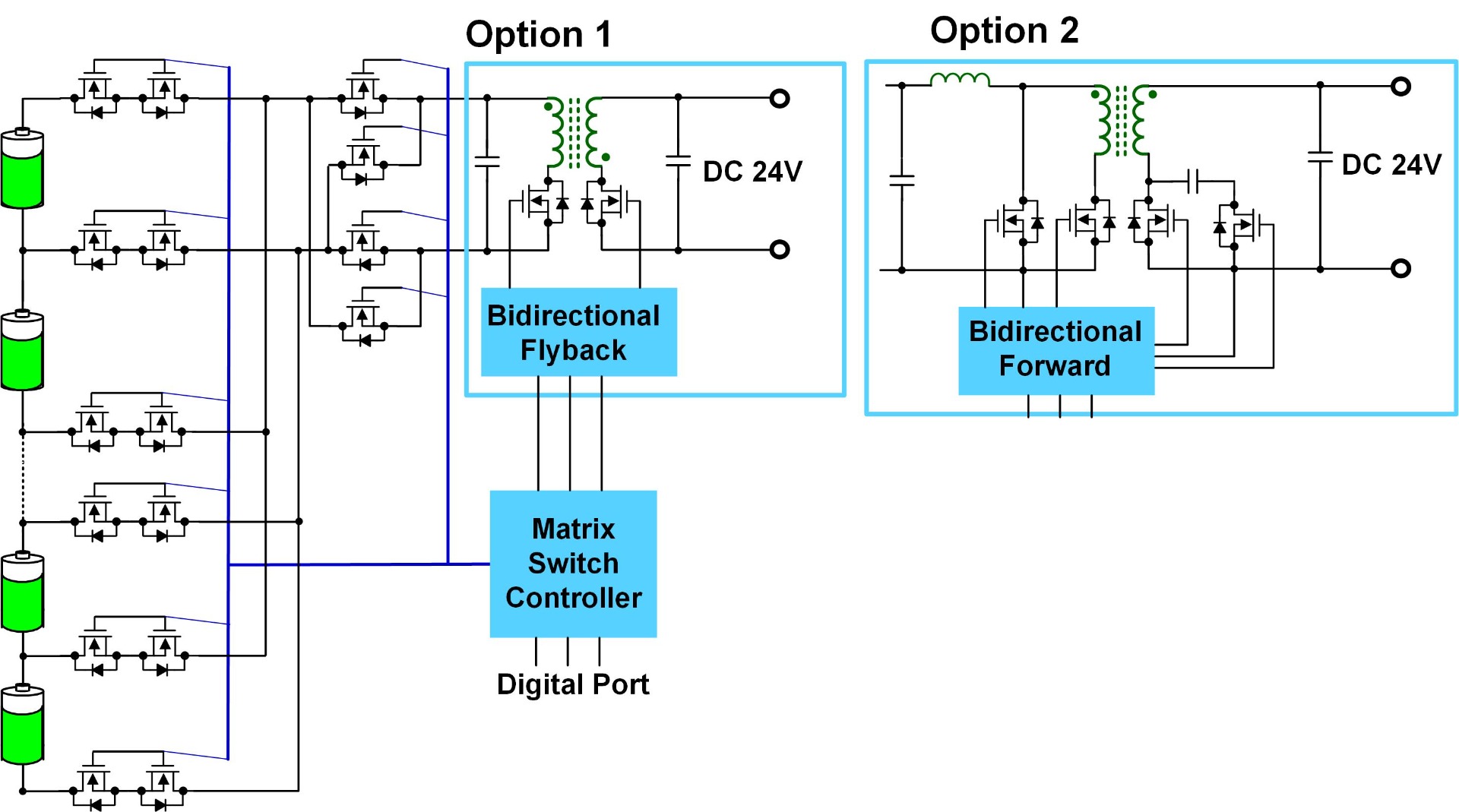
Figure 4: Switch Matrix Based Bidirectional DC/DC Active Balancer
Bidirectional Buck-Boost Active Balancer
A buck-boost active balancer takes a simpler approach by leveraging commonly used buck and boost battery charger technology. Rather than moving charge to various locations along a battery stack or to a separate power rail, buck-boost active balancing moves charge to directly adjacent cells. This greatly simplifies the balancing circuitry and leverages the simultaneous operation of many balancers to distribute charge across the entire stack.
A 2-channel buck-boost balancer provides bidirectional charge movement between two adjacent cells by operating in buck-balance mode or boost-balance mode. By placing a 2-channel buck-boost balancer on every pair of cells, charge can be moved throughout an entire pack (see Figure 5).
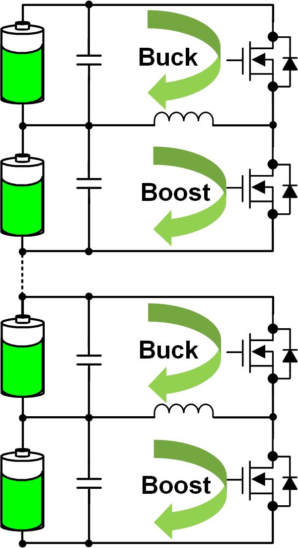
Figure 5: Bidirectional “Buck” and “Boost” Active Balancer
Compared to the two previous active balancers, a 2-channel buck-boost active balancer follows a simple process:
- In buck-balancing mode, the active balancer transfers energy from the upper cell (CU) to the lower cell (CL).
- In boost-balancing mode, the active balancer transfers energy from the CL to the CU.
Among the three types of active balancers, the bidirectional buck-boost active balancer is the simplest and most reliable. Table 1 compares all three active balancing methods.
Table 1: Different Active Balancing Methods
| Advantages | Disadvantages | |
| Bidrectional Flyback |
|
|
| Matrix Switch |
|
|
| Buck-Boost |
|
|
Design Example
The MP264x family (MP2641, MP2642, and MP2643) are highly integrated, bidirectional buck-boost active balancers that provide up to 3A of charge redistribution between two series lithium-ion cells (see Figure 6). These devices can be used for all common lithium-ion battery chemistries, such as NMC, NCA, Li-polymer, and LFP. The MP264x efficiently moves charge between cells to minimize balancing time and heat generation. The MP264x can also compensate for mismatched cell capacities to extend battery runtime. To guarantee safe operation, the MP264x provides CL and CU over-voltage protection (OVP) and under-voltage protection (UVP), as well as thermal shutdown. The MP264x family is available in QFN-26 (4mmx4mm) packages.
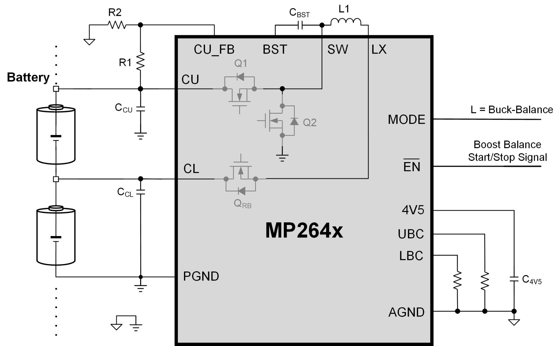
Figure 6: MP264x Typical Application Circuit
Configuring the MP264x is simple:
1. Set the buck-balancing current (IUBC). IUBC can be configured between 0.5A and 2.5A via an external resistor (RUBC, in kΩ) connected between the MP264x’s UBC and AGND pins. IUBC can be calculated with Equation (1):
$$I_{UBC}= \frac{640}{3 \times R_{UBC}}$$2. Set the boost-balancing current (ILBC). ILBC can be configured between 0.5A to 3A via a resistor (RLBC, in kΩ) connected between the MP264x’s LBC and AGND pins. ILBC can be estimated with Equation (2):
$$I_{LBC}= (\frac{V_{CUη} \times V_{CL}}{η \times V_{CL}}\times \frac {640}{3 \times R_{LBC}})$$Where VCL is the lower cell voltage (between CL and AGND), and VCU is the voltage of both series cells (between CU and AGND). Both VCL and VCU refer to voltages measured without balancing enabled. η is the converter’s boost-balance efficiency; since this efficiency depends on cell voltage, an appropriate value should be selected (see Table 2).
Table 2: η Selection
| VCL(V) | η |
| < 3.65V | 0.89 |
| ≥ 3.65V | 0.91 |
By combining multiple MP264x devices together, active balancing can be scaled to any number of series cells, and charge can be redistributed to and from any cells within the pack. Figure 7 shows the active balancing example for 4-cell batteries with three MP264x devices in series.
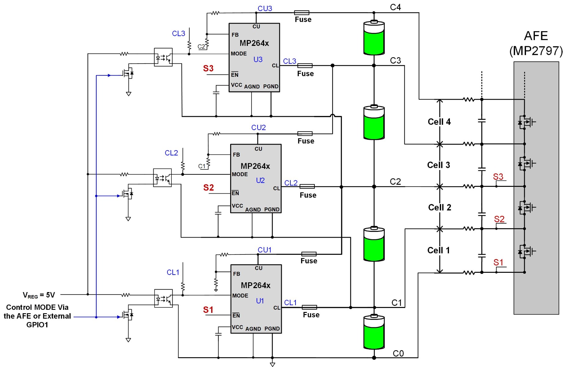
Figure 7: Typical Application Circuit in an ESS
Conclusion
With a growing demand for safer, more energy efficient, and longer lasting lithium-ion battery systems, there is a growing demand for better cell balancing. Passive balancing, which is limited to small currents that simply dissipates energy, is no longer sufficient to meet these demands. As a result, active balancing solutions are increasingly being adopted for their high-current, fast cell balancing advantages. In particular, bidirectional buck-boost active balancers (such as the MP2641, MP2642, and MP2643) offer simplicity and reliability. Explore MPS’s active balancers to find the best solution for your application.
_______________________
Did you find this interesting? Get valuable resources straight to your inbox - sent out once per month!
Technical Forum
 Latest activity 9 hours ago
 2 Comments
Latest activity a day ago
1 Comment
Latest activity 2 days ago
1 Comment
2 Comments
Latest activity a day ago
1 Comment
Latest activity 2 days ago
1 Comment
Log in to your account
Create New Account