AN214 - MPSmart User Guide

Get valuable resources straight to your inbox - sent out once per month
We value your privacy
Instructions
This user guide is to help users understand and utilize the powerful features and capabilities of MPSmart software. MPS distributes the MPSmart simulation tool under license from SIMPLIS Technologies. This software integrates SIMetrix and SIMPLIS simulators, providing users with a comprehensive simulation and analysis tool for MPS products.
Overview of MPSmart
MPSmart is a powerful software tool that allows users to select and download suitable MPS IC models, simulate the chosen IC models, and analyze the performance of their designs. With its user-friendly interface, MPSmart makes it easy for users to develop advanced designs with using large library of MPS recommended schematics and models.
MPSmart includes two simulators, SIMetrix and SIMPLIS. SIMetrix is a fast and accurate SPICE type simulator. SIMPLIS is a circuit simulator specifically designed to handle the simulation challenges of switching power systems. Most MPS product IC models are created with SIMPLIS. This application note will mainly introduce MPSmart models built on SIMPLIS simulator.
SIMPLIS supports three types of simulations, POP (Periodic Operating Point) simulation, frequency-based AC simulation, and transient simulation. All the simulations will be introduced in the Running a Simulation section on page 12.
Features and Benefits
MPSmart offers several key features and benefits for users, which are listed below:
- Allows users access to a wide range of MPS IC models, allowing users to design and optimize diverse power electronic controllers.
- Provides support for useful simulation types. Aside from normal time domain-based transient analysis, MPSmart provide small-signal analysis for the switching circuit, so there is no need for error-prone average modes.
- Gives users full schematic capture and editing capabilities.
- Provides advanced applications and customization options. The MPS Design Assistant spreadsheet and MPS GUI expand the MPSmart application range. See the Advanced Applications section on page 16 for more details.
- Includes comprehensive troubleshooting and support resources.
System Requirements
MPSmart operates on Microsoft Windows platforms. MPSmart is fully supported by Windows 10 (64-bit) and above.
Please note that the performance of MPSmart may be affected by computer hardware and complexity of designs. It is recommended to use a system with higher specifications for large or complex projects.
Getting Started
This section describes the process of downloading, installing, and launching MPSmart for the first time, and allows the user to become familiar with the user interface.
Downloading, Installing, Launching, and Upgrading MPSmart
Download and install the MPSMart software on the computer. The MPSmart software can be downloaded from the MPS website: https://www.monolithicpower.com/en/mpsmart-v8.html.
After downloading and installing MPSmart on the computer, launch MPSmart by double-clicking the shortcut on the desktop or in the Start menu. Figure 1 shows the MPSmart main window.
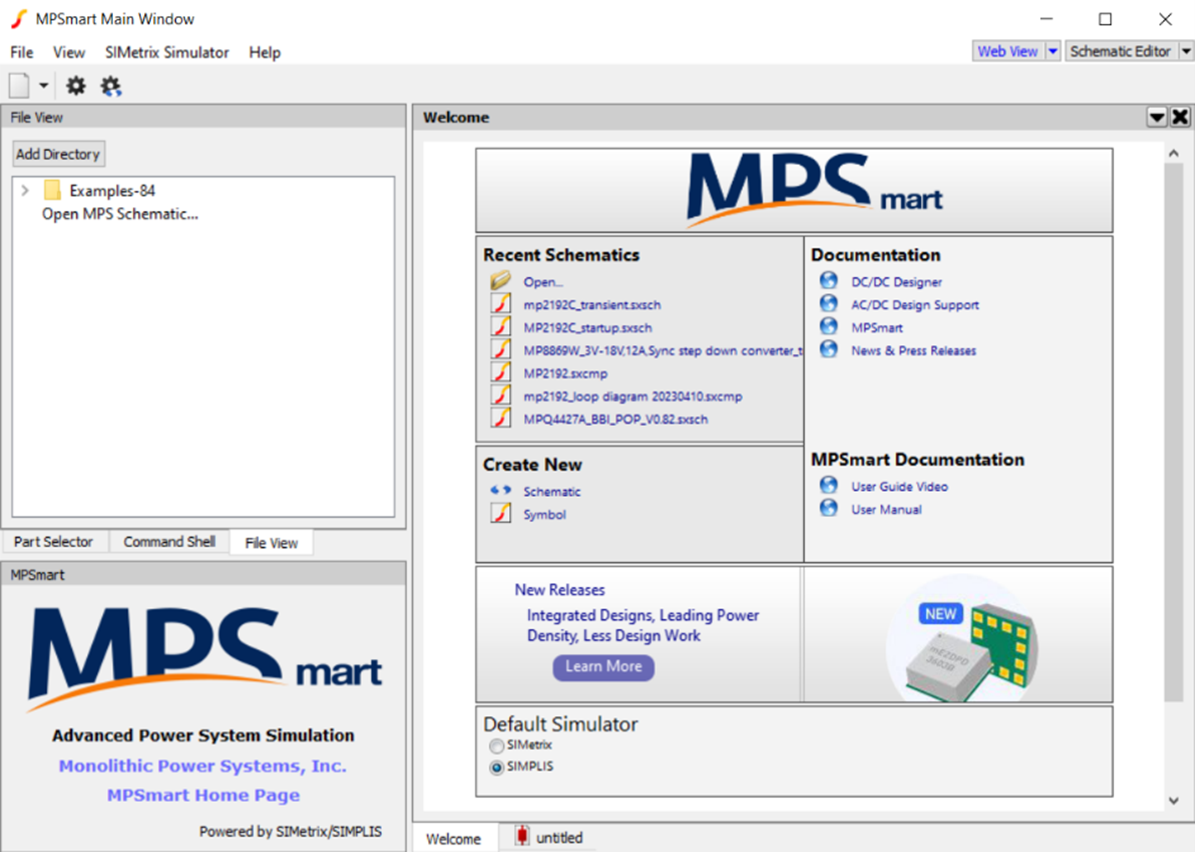
Figure 1: MPSmart Main Window
MPSmart is upgraded at least once a year with updated features and the latest MPS product model libraries. Users can check for updates or reinstall the software to receive full support.
User Interface Overview
The main user interface consists of two parts: System View and Workspace View. On the left side of the MPSmart window, System View provides tools to operate the program. Workspace View provides a means for developing and reviewing designs, including the schematic editor and waveform viewer.
Figure 2 shows an overview of the user interface.
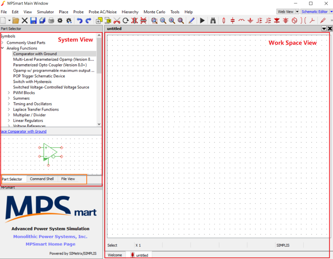
Figure 2: Overview of the User Interface
Figure 3 shows the sections of System View, which include Part Selector, Command Shell, and File View.
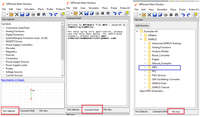
Figure 3: System View (Part Selector, Command Shell, and File View)
Part Selector: Part Selector covers most of the component categories. Users can select components from the Part Selector section to place on the schematic to start a design.
Command Shell: Command Shell displays the status of the software performing actions or executes scripts.
File View: File View displays a hierarchical list of files and folders. “Examples” is the default folder that is automatically installed with MPSmart. In the default example folder, click the folder titled “MPS” that contains the MPS product model.
Under File View, click the “Add Directory” button to choose the frequently accessed folder to add it to the File View list. Users can also open, rename, delete, or manage the folders and files in the File View panel.
Figure 4 shows Workspace View, which provides the means to develop and review designs, including the Schematic Editor and Waveform Viewer.
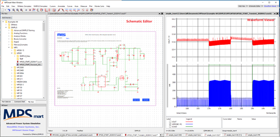
Figure 4: Schematic Editor and Waveform Viewer
Schematic Editor.: Users can create and modify circuit designs in Schematic Editor. This editor allows users to place components, connect wires, and adjust component values. Users can also right-click on components within Schematic Editor to access additional options and commands, such as disabling components, editing and adding properties, or editing and updating symbols.
Waveform Viewer: Waveform Viewer is a dedicated area for viewing and analyzing the waveforms generated during simulations. Users can use Waveform Viewer to check the performance of the design, compare different simulation runs, and measure critical parameters (e.g. voltage, frequency, and duty cycle).
These user interfaces make it easy to navigate MPSmart and access its key features. The following sections of this manual provide detailed instructions on how to use MPSmart's various tools and functions.
Selecting and Downloading MPS IC Models
This section guides users through the process of selecting and downloading MPS IC models for use in designs. It discusses how to access the MPSmart example folders, browse the product page, download MPS IC models, and get help from MPS support teams.
Accessing MPSmart Example Folder
As mentioned in the User Interface Overview section on page 4, users can access MPS IC models through the MPSmart example folder, which is automatically installed with MPSmart. Follow the steps below to access the IC models in MPSmart:
- Launch MPSmart and open File View (located on the left side of the window).
- The folder titled “MPS” contains pre-installed IC models, typical schematics, and example projects for various MPS products (see Figure 5). Expand and browse the file’s contents to find the desired MPS IC model example project.
- Double-click on the desired IC model schematic to open it in Schematic Editor.
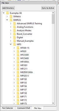
Figure 5: MPSmart Example Folder
Browsing on the MPS Website
To find the appropriate MPS products for the application and to download the correct IC model, visit the MPS website: https://www.monolithicpower.com. Use the search bar to enter the part number of the desired MPS IC, or navigate to the Products tab in the main menu to view the product categories and access the corresponding product pages.
Figure 6 on page 8 shows an example of how to find MPSmart models on the MPS website. For example, to find the MPM3595-25’s MPSmart model, enter the part number “MPM3695-25” in the search bar, then click on the part number to navigate to the MPM3595-25’s product detail page. Once on the detail page, scroll down to the Design Resources section. Click on “MPSmart Model” to download the MPSmart model.
This should download a zip file containing the model files and associated documentation for the part.
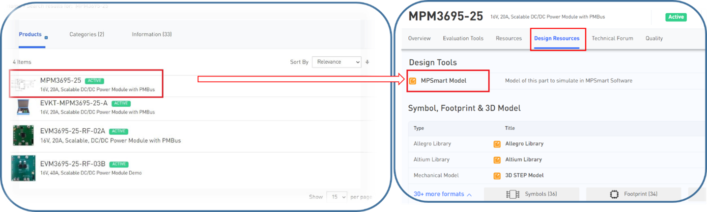
Figure 6: Finding MPSmart Models on the MPS Website
Obtaining Assistance from MPS Support Teams
Another way to obtain the latest IC models is to contact an MPS FAE. They can provide users the required files, and can help users start their design.
The online technical forum is also a good contact window (see the Contacting Technical Support section on page 33).
For further support, send an email to the simulation team at mps-simulation@monotlithicpower.com.
Intranet users can find most of the design resources on the intranet.
Basic Operations
This section discusses the basic operations of the MPSmart software, including navigating through the typical application schematics for MPS products, as well as how to create a new project with an MPS IC model.
Navigating Typical Schematics for MPS Products
The MPS simulation team provides various typical application schematics for each MPS IC model to help users start their design. As described in the User Interface Overview section on page 4 and the Selecting and Downloading MPS IC Models on page 7, users can locate the MPS IC models in the pre-installed MPSmart “Examples” folder, download the models from the MPS website, or ask MPS technical support to provide the models.
A typical application schematic for a circuit in Schematic Editor consists of six sections (see Figure 7).
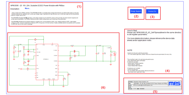
Figure 7: Typical Schematic for an MPS IC Model
- Description: This section provides a brief introduction to the IC, including basic information such as product specifications, application range, control strategy, and package information. Clicking on “More” opens the product detail page on the MPS website, where users can find comprehensive information on the part (see Figure 8 on page 10).
- Design Support: This button opens the Design Tool page on the MPS website. Users can explore and use various design tools provided by MPS to facilitate the design process (see Figure 9 on page 10).
- Contact Us: The "Contact Us" button opens the regional contact information page for technical support and assistance.
- Model notes: This section provides helpful information about the IC model, such as built-in performance features and how to use any accompanying documentation.
- Model information: This block displays basic information about the IC model, including the version, date of creation, and author.
- Typical application schematic: This section provides a fully verified circuit design that can be used for direct simulation to evaluate an application’s performance. By adapting and modifying the typical application schematic, users can speed up the design process and test the project using a proven application platform.
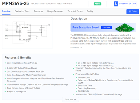
Figure 8: Click ‘More’ to Open the IC Detail Page
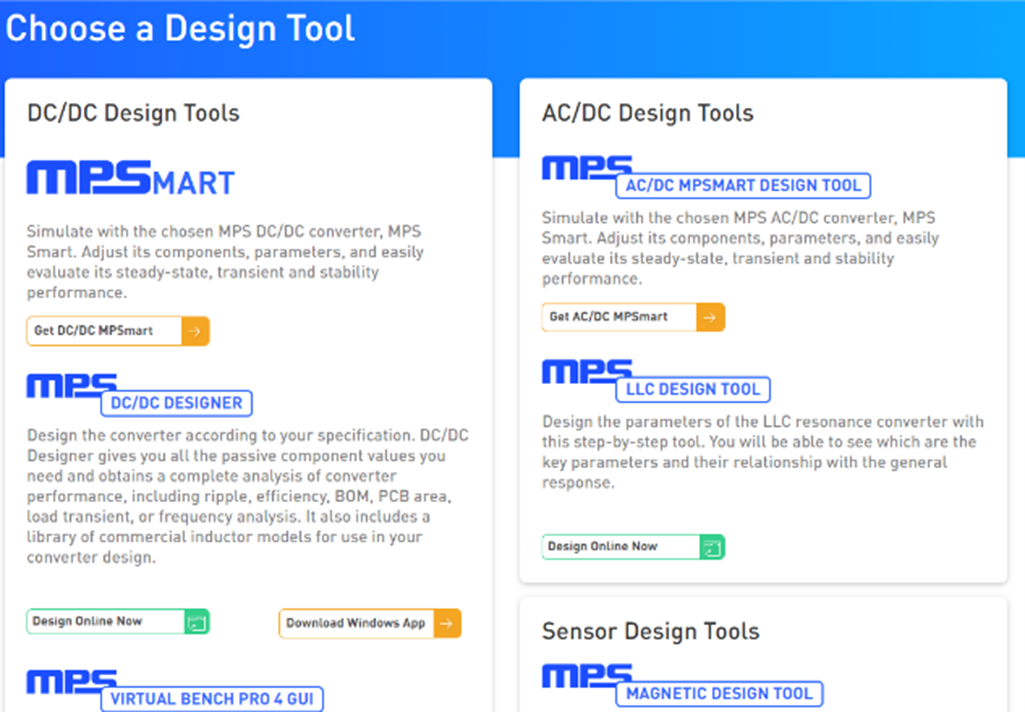
Figure 9: Design Tool Page
Creating a New Project with an MPS IC Model
An easy way to start a new project with an MPS IC model is to implement the design based on the typical application schematic, as discussed in the Navigating Typical Schematics for MPS Products section on page 9. Adapting and modifying the schematic can accelerate the design process.
Another option is to create a new design by clicking “File” in the main menu, and then selecting “New/SIMPLIS Schematic” or “New/SIMetrix Schematic”. Save the schematic to the folder. Most MPS IC models are SIMPLIS models, while a few are SIMetrix models.
Select the MPS IC model from the model library to start designing the schematic. Click “Place From Model Library” to add additional components, such as resistors, capacitors, sources, and semiconductor devices (see Figure 10).
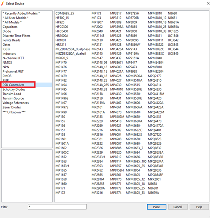
Figure 10: Model Library
Arrange and connect the components in the schematic as required for the design. Now the new project with the MPS IC model is ready for simulation analysis.
In addition to obtaining MPS IC models from the MPSmart model library, users can find more from the MPS website or field support (see the Selecting and Downloading MPS IC Models section on page 7 for more details).
_______________________
Did you find this interesting? Get valuable resources straight to your inbox - sent out once per month!
Technical Forum
 Latest activity a day ago
 1 Comment
Latest activity 7 days ago
5 Comments
Latest activity 7 days ago
2 Comments
1 Comment
Latest activity 7 days ago
5 Comments
Latest activity 7 days ago
2 Comments
Log in to your account
Create New Account