MP3424 Single AA Battery Boost Solution

Get valuable resources straight to your inbox - sent out once per month
We value your privacy
Boosting to 5V from AA Battery
A single AA battery is a very convenient power source for portable low-power applications. A typical AA battery has a 2 ampere-hour capacity, and can supply peak currents of over 2A. The battery can typically supply 1.5V when fully charged, down to 0.9V when discharged. This does not include the internal resistance drop, which can be between 100mΩ and 120mΩ. To convert that voltage range to a regulated voltage of 3.3V or 5V, there are many DC/DC boost converters designed to start up and operate from a low input voltage. These devices have synchronous switches, so that a low-side switch can energize the inductor. Then the high-side switch transfers the stored energy to the output capacitance and load.
One example of a AA boost converter is the MP3414, which has a 1.5A low-side switch that can boost to a 3.3V output, and a 400mA load from a minimum battery input of 0.9V. Figure 1 shows the MP3414 circuit. The synchronous high-side switch replaces a discrete diode in the circuit, and also provides current limiting and input/output isolation under short-circuit and fault conditions.
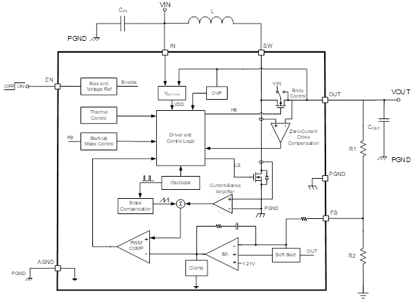
Figure 1: Synchronous Boost Converter Schematic
While the MP3414 is a good solution for a standalone single AA or 3.3V solution, the maximum output voltage is limited to 4.0V, and the switching current limit (1.5A) is below the maximum current that the battery can deliver.
For higher output voltage and load applications, there are boost DC/DC converters with higher maximum current and voltage specifications, although their input voltage range may be limited. For example, the MP3424 has up to a 9.5A switch current and a 5.5V output voltage. It also has a minimum 2.0V start-up voltage, and a minimum 1.6V operating voltage. From these specifications, it appears the MP3424 may not be suitable for a single-cell AA battery application; however, with special circuit techniques and system set-up, a useful solution is possible.
Higher-Power AA Boost Circuits
Boost converter circuits allow the switching power path to be separated from the input bias, and having a low-power auxiliary supply enables a high-current boost design. Figure 2 shows the MP3424, which has a circuit that separates the switching current path from the input bias.
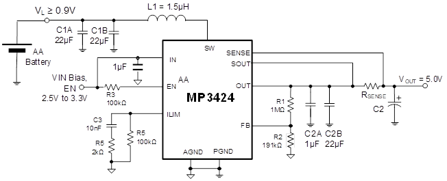
Figure 2: Single-Cell, High-Current Boost Converter
The MP3424 input and enable pins take very little current, and if the output is regulated above 3V after start-up, the device is then biased from the output. This means a secondary supply for that bias could be a small 3V lithium battery, a secondary DC/DC converter, or a charge pump device using the AA battery.
The MP3424 has a high switching current limit with a 9.5A maximum, but there is a current-sense circuit that yields an adjustable maximum output current. The AA battery’s internal resistance limits the peak current to about 3A maximum, and about 2A at a 0.9V input (ESR loss of 0.1Ω x 2A = 0.2V, for a 0.7V actual input). RSENSE can be calculated with Equation (1):
$$I_{OCL} = V_{OCL} / R_{SENSE}$$Where IOCL is the output constant current limit, and VOCL = 30mV.
For a 400mA current limit, RSENSE is 0.075Ω. When the device load increases to the current limit, the peak switching current is limited to support that current, which is about 3A with a 5V output. As a result, the output voltage begins dropping. The output voltage stays at a lower constant voltage, while the AA battery maintains a safe peak current. If the load increases, the output eventually drops below the input, and the high-side MOSFET conducts current to the load. If VOUT drops below 50% of the expected output, the device goes into short-circuit limiting, shuts down, and retries every 40µs.
An Excellent Portable Pulse Power Supply
The constant current function can be useful for intermittent peak pulse power needs in portable devices. Many applications require the sensors, processor, and memory to operate for a short time period, then shut down and repeat. This process can be repeated anywhere from hundreds of times per second to just once per second. Because the power needed can eclipse the peak capabilities of the single AA battery, another solution is to boost to a higher voltage and store charge in a capacitor between bursts. This allows the capacitor to discharge during the burst, then recharge.
Figure 3 shows an example application for a peak pulse power system.
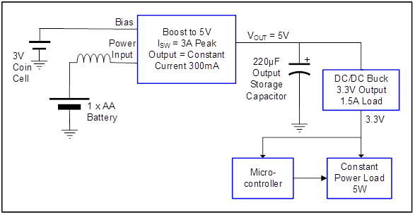
Figure 3: Peak Pulse Power System
Figure 3 shows an example application for a peak pulse power system.
In this application, the load is constant at 5W for 100µs (e.g. IR LEDs), with an initial voltage of 5V that repeats every 1.0ms. The MP3424 boosts one AA battery and has a 1.5µH inductor. There is a 220µF electrolytic output storage capacitor. The switching frequency is fixed at 580kHz, and the output current limit is set to a constant 0.3A to charge the output capacitor. Delivering a constant 5W with a discharging capacitive source results in a discharge curve (see Figure 4). The simulated curve includes the capacitor’s 30mΩ series resistance.
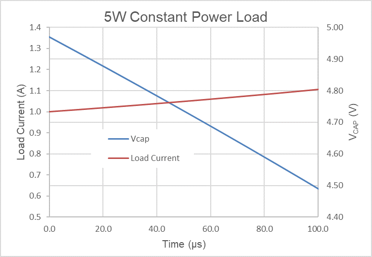
Figure 4: Discharge Curve
Note that the MP3424 can be can be boosted during the discharge time, but the MP3424 is disabled in this example, with the load current supplied solely by the capacitor. Since the output is a constant power and the source voltage to the load is dropping, the current from the capacitor increases with time. After discharging, the capacitor’s voltage is about 4.5V.
The capacitor is charged by enabling the MP3424 with a 300mA constant current output. Using dt = C x dV / I, the recharge time is calculated to be (220e - 6 x 0.5) / 0.3 = 367µs, which returns the capacitor to 5V with extra time to spare within a 1ms cycle time. Once the output reaches 5.0V, the MP3424 changes to low-load current pulse frequency modulation (PFM) mode, reducing battery drain. The MP3424’s current control keeps the peak battery current at about 1.5A during the charge cycle, preventing the battery voltage from dropping excessively due to ESR.
Charging Supercapacitors
Another high peak current application must hold the charge for very long time between discharges, eliminating any battery drain. This particular application requires a constant power of 2.0W with a discharge time of 500ms, and a second discharge 2 seconds after the first. The system can then then be idle for up to a month. The same MP3424 circuit in Figure 2 with a 5V output can be paired with a 0.5F supercapacitor (SC) for the longer discharge time. The SC has a much higher ESR (about 0.4Ω), so there is a drop at the input to the buck regulator. This drop is about 0.25V during the discharge period. The terminating voltage is about 4.1V, and there is a 300mA constant current during the 1-second recharge time. With the discharge time and charge time of 1.5 seconds, the conditions for the 2-second cycle time are met.
Since there are leakages at the MP3424 output and sense pins, the supercapacitor slowly discharges over a month of inactivity when the device is disabled (to preserve the battery). For this application, an output P-channel switch isolates the SC from the boost circuit, and is controlled by the enable signal used by the microcontroller to start the discharge/charge cycle. A combination of N-channel and P-channel devices in a single package performs the switching with the enable high signal, and reduces off leakage at the supercapacitor to below 50nA. Figure 5 shows the whole circuit.
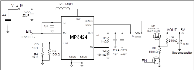
Figure 5: Supercapacitor Charging Circuit for Peak Pulse Power
Conclusion
Having a programmable constant current mode in a boost DC/DC regulator is a great tool to use for applications that have a power-limited source, such as a low-voltage battery. Using the switch pin on the boost converter for a separate power input, while biasing the device with a small auxiliary source, utilizes the full power potential of the battery source.
_________________________
Did you find this interesting? Get valuable resources straight to your inbox - sent out once per month!
Related Forum Topics
 Latest activity 3 years ago
 2 Comments
Latest activity 3 years ago
2 Comments
Latest activity 5 years ago
6 Comments
2 Comments
Latest activity 3 years ago
2 Comments
Latest activity 5 years ago
6 Comments

Log in to your account
Create New Account