How to Design a Thermally Balanced Current-Sharing System for Multi-Phase Power Designs

Get valuable resources straight to your inbox - sent out once per month
We value your privacy
Introduction
The car of tomorrow is envisioned to be an audiovisual wonderland on wheels, including wraparound screens and dozens of speakers. Driving on the road in the future will immerse passengers in an incredible sensory experience with content streamed via ultra-fast 5G. To achieve this content-rich, connectivity-heavy paradigm of future mobility, emerging digital cockpit systems continue to demand exponentially greater computing capability. These increasing computing requirements consequently result in a demand for higher power.
As such, interleaved topologies are gaining popularity because they can supply higher load currents while improving EMC. However, engineers must optimize the balance between thermals, board size, and cost when designing these automotive power management systems. In particular, it is vital to achieve optimal current sharing between phases to avoid overheating the MOSFETs in one phase, as this can degrade the entire system.
This article proposes a novel, cost-effective approach to achieve a high-power, offline battery (12V) power management stage that multi-phases two buck controllers. The solution combines a simple yet elegant thermal-balancing circuit with two interleaved MPQ2908A-AEC1 devices, which are 4V to 60V input, current-mode, synchronous step-down controllers. This system effectively improves current sharing between phases while adeptly addressing the higher power dilemma.
Power Stage
As the power demand of new automotive designs continues to rise, power electronic engineers face the challenge of designing circuits that can deliver more power without increasing PCB size and cost. In addition, these circuits must maintain low EMI below the regulated values.
Multi-phase topologies provide a simple solution to overcome this design challenge. In a multi-phase topology, multiple power converters are placed in parallel to increase the available load current of the entire power supply unit (PSU), which increases the amount of deliverable power. Moreover, if all of the converters run synchronously with each other but in different locked phases, then the EMI generated by the overall system is decreased. Lastly, the current demanded by the load is shared by all of the converters, which optimizes thermal behavior.
The automotive power management system presented in this article uses a dual-phase power supply that steps down the 48V common in new automotive designs to the 12V that is demanded by many advanced driver assistance systems (ADAS). To incorporate high 20A load currents, this design uses two MPQ2908A-AEC1 devices. In addition to this controller’s wide input range, which can step down from the 48V specification, this device can be implemented in dual-phase topologies using its SYNCO pin, which outputs a 180° out-of-phase clock.
Figure 1 shows the system’s block diagram for the original 240W power stage. First, there is a 48V car battery. Second, a system with reverse polarity protection and over-voltage protection (OVP) is added to protect the system from damage in the event of undesired events (e.g. incorrect cable connections). Lastly, an EMC filter reduces the conducted emissions, while the dual-phase interleaved buck converter steps down the voltage from 48V to 12V. Since the power managed by the system is quite high, a frequency spread spectrum (FSS) modulator is added to achieve low EMI in the overall system.

Figure 1: Original 240W Power Stage
Design Challenges and Proposed Solutions
Designers face two key design challenges due to the increasing power demands in the automotive sector. First, the power supplies for automotive applications must meet standardized EMC requirements, such as CISPR 25 Class 5. This means that the PCB layout should incorporate all EMC design recommendations. Furthermore, to ensure that this 240W system can stay within the regulated EMC limits, certain complementary solutions are utilized (including an interleaved topology, EMC filter, and FSS modulator).
Designs must also manage board thermals. It is recommended to choose the appropriate circuit components to achieve high efficiency levels. By increasing efficiency, designers can reduce power loss, which minimizes temperature rise. In particular, designers should carefully select the MOSFETs and inductor(s) in their system.
Figure 2 shows the efficiency of the original 240W power stage at four different input voltages: 24V, 36V, 48V, and 60V.
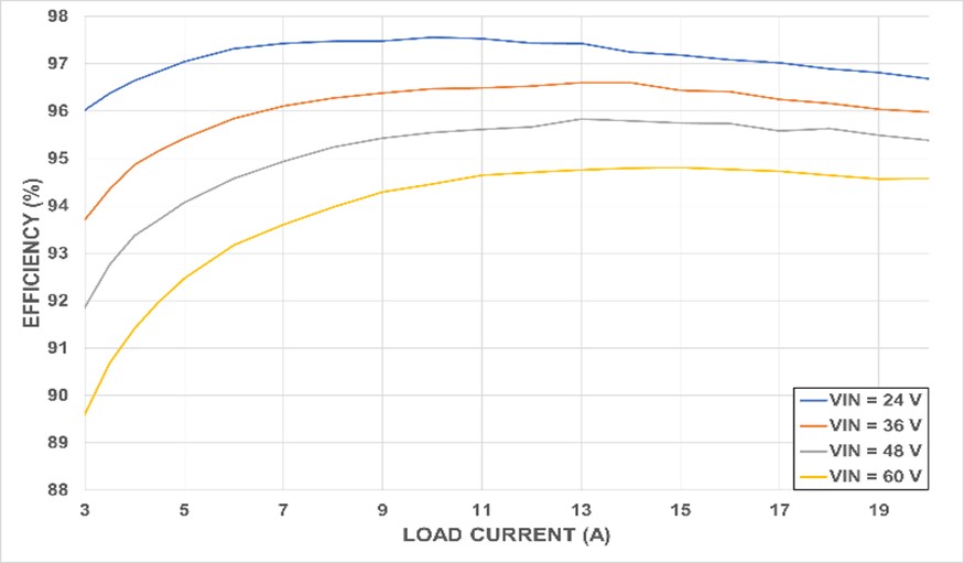
Figure 2: System Efficiency
There are other ways to improve the automotive power management system thermals beyond selecting optimal components. For example, the MPQ2908A-AEC1 allows the designer to select the converter’s switching frequency (fSW). In general, fSW should be as low as possible to reduce switching losses. A lower frequency increases efficiency while reducing thermal overheating for the board. For this example, with fSW set to 225kHz, the higher EMI peak is placed at 450kHz (2 x fSW) to reduce the switching losses without impacting EMC.
Apart from the thermal and EMC constraints, interleaved topologies typically require excellent thermal distribution to equalize MOSFET degradation and prevent parts of the board from overheating. To overcome this thermal constraint, it is vital to select an appropriate PCB layout and optimize current sharing between the two controllers. With an optimal current-sharing scheme, the load current is equally distributed between all of the converters in the system. Therefore, all of the MOSFETs have the same thermal rise.
Consider a system without thermal balancing. For a system in steady state with a 20A load current, there is a 1A difference between the averaged current of each phase (denoted as the light blue and green traces in Figure 3). This results in an unbalanced temperature for both phases. If there is suboptimal thermal distribution between the phases (phase temperatures denoted as the dark blue and pink traces in Figure 3), then the hotter phase may experience faster degradation.
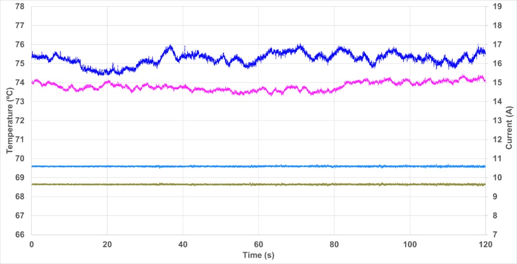
Figure 3: Current Sharing without a Thermal-Balancing System
Thermal-Balancing System
For this article, we designed a simple and easy circuit that equalizes the temperature for both phases via accurate temperature-sensing. This circuit is incorporated into the original 240W system, then it senses and compares the temperatures of the two phases. As a result, the load current supplied by each converter can be changed accordingly (see Figure 4).
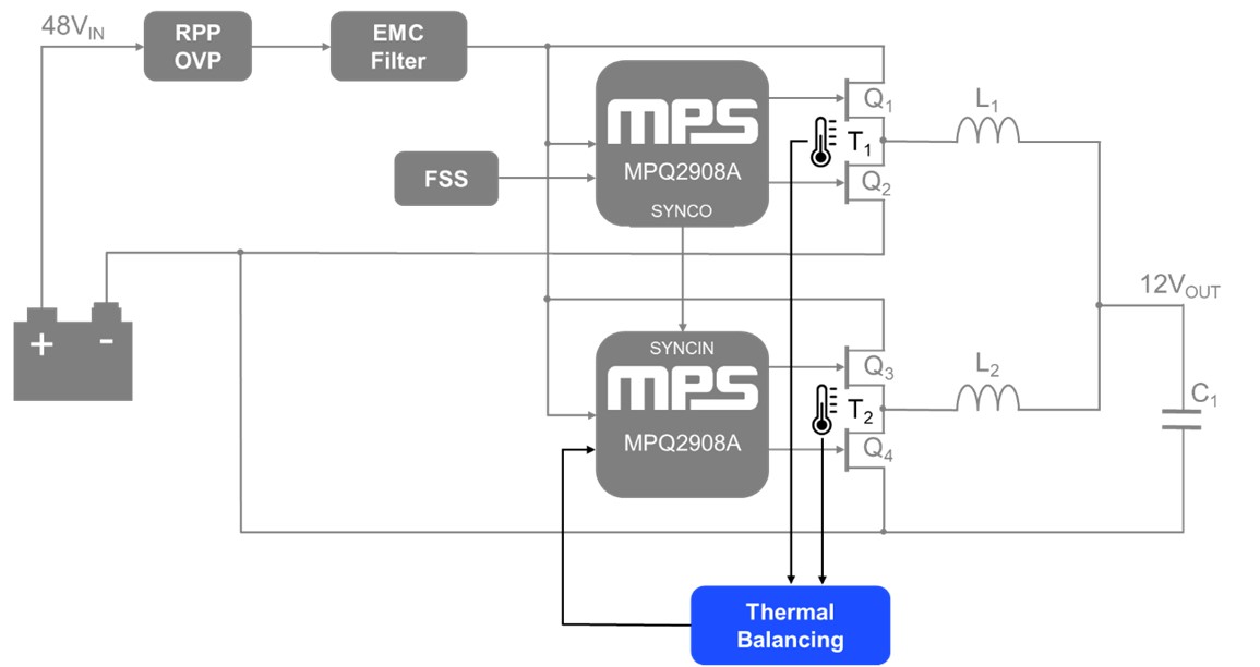
Figure 4: 240W Power Stage with Thermal-Balancing System
For example, if T1 > T2, the thermal-balancing system modifies phase 2’s compensation signal to increase its output voltage (VOUT2). Since the total output current is fixed by the load, the phase 2 current (IPHASE2) increases while the phase 1 current (IPHASE1) decreases. Thus, the power dissipation and temperature of phase 1 decreases until T1 is equal to T2.
Furthermore, this circuit reduces the BOM cost and minimizes the MOSFET and inductor size. If the current is shared unequally between the two phases, then the designer must use physically larger circuit components, such as the MOSFETs and inductor(s), to withstand the larger currents and power caused by current measurement tolerances. When current is shared equally between phases, the design can be optimized for physically smaller MOSFETs and inductor(s), thereby reducing BOM cost.
In this circuit, the temperatures of the two phases are sensed via two negative temperature coefficient (NTC) thermistors. Then the temperature difference is fed to a proportional-integral (PI) control circuit that outputs a signal to phase 2’s compensation (COMP) pin. If T2 < T1, then the voltage on phase 2’s COMP pin increases along with the current (or vice versa if T2 > T1).
Phase 1 is not connected to the thermal-balancing circuit. The output current (ILOAD) is the combination of both phase currents (IPHASE1 + IPHASE2) and is set by the load, independent of the current distribution in the phases, as demonstrated with Equation (1):
$$I_{LOAD} = I_{PHASE1} + I_{PHASE2}$$Because of this, if IPHASE2 decreases due to thermal balancing control, then IPHASE1 automatically increases (and vice versa). As a result, phase 1 is influenced by the thermal-balancing circuit despite not being directly connected to it.
Figure 5 shows the thermal balancing schematic design.
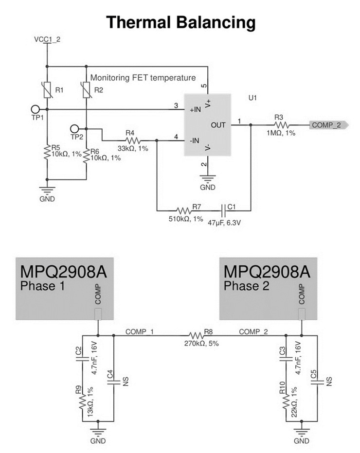
Figure 5: Thermal Balancing Schematic Design
A resistor (R8) placed between phase 1 and phase 2’s COMP pins ensures that that the current difference between the two phases does not reach critical or dangerous levels. The experimental results identified 270kΩ as the optimal value for R8.
The simplified circuit only requires correctly sizing the PI circuit components to achieve temperature control. The PI’s circuit transfer function (H(s)) can be calculated using Equation (2):
$$H(S) = \frac {V_{OUT}(s)} {V_{IN}(s)} = - (\frac {R_7}{R_4} + \frac {1}{R_4 \times C_1 \times s})$$Where C1, R4, and R7 are the components of the PI compensation loop.
The proportional gain of the PI circuit (KP) can be calculated using Equation (3):
$$K_P = \frac {R_7}{R_4}$$The integral gain of the PI circuit (KI) can be calculated using Equation (4):
$$K_I = \frac {1}{R_4 \times C_1}$$Results
By using a thermal-balancing system, drastic improvements in current sharing and temperature equalization can be observed. Specifically, the temperature difference shown in Figure 3 (about 2°C) drops to less than 0.5°C (denoted as the dark blue and pink traces in Figure 6).
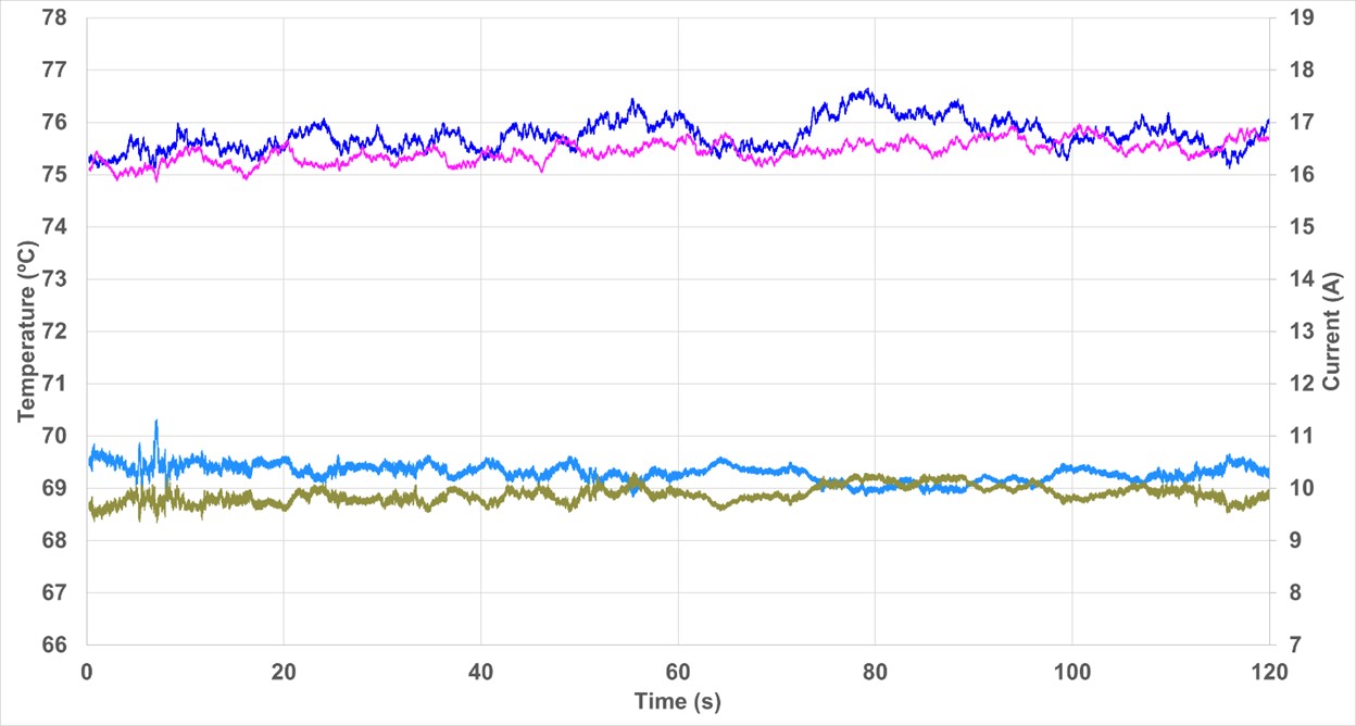
Figure 6: Current Sharing with a Thermal-Balancing System
Conclusion
New automotive designs are adopting 48V power management systems to reduce weight and power loss in the vehicle’s cable harnesses. Moreover, to withstand high loads, the use of interleaved topologies is important for the increase in required power.
When using interleaved topologies, excellent thermal distribution is necessary to balance the MOSFET degradation. This article presented a simple and easy thermal-balancing circuit combined with the MPQ2908A-AEC1, which improves current sharing and temperature distribution in multi-phase designs, and meets standardized EMC requirements, such as CISPR 25 Class 5. The temperature difference between the multi-phase converter phases can be effectively reduced from 2°C to 0.5°C using well-known and commonly used components.
_______________________
Did you find this interesting? Get valuable resources straight to your inbox - sent out once per month!
Technical Forum
 Latest activity 2 days ago
 2 Comments
Latest activity 3 days ago
2 Comments
Latest activity 2 weeks ago
3 Comments
2 Comments
Latest activity 3 days ago
2 Comments
Latest activity 2 weeks ago
3 Comments
Log in to your account
Create New Account