A Brief Primer on MPSafeTM, MPS’s Process to Functional Safety Automotive Development

Get valuable resources straight to your inbox - sent out once per month
We value your privacy
Introduction
MPSafeTM is a new, advanced safety development process for automotive components from Monolithic Power Systems. This process has been independently certified to meet the criteria laid out in ISO26262, a standard that applies to the design, development, and production of automotive functional safety products.
The automotive industry is making rapid advances in the pursuit of an autonomous, connected, and electrified future of transportation where driving becomes a task entrusted to intelligent, sensor-rich computer systems. To this end, the industry is constantly evolving — safety standards are becoming ever more stringent, specific, and novel. For such safety-critical automotive applications, MPSafeTM governs all relevant integrated circuit (IC) development at MPS to ensure that suitable products can accommodate these standards.
Automotive Standards: AEC-Q100
Automotive companies sell millions of vehicles each year, and the failure of a single component or subsystem that is used across a fleet of vehicles can lead to danger, legal issues, and serious injuries to consumers. While not all vehicle functions offer the same safety features (e.g. a video player won’t require the same safety features as the braking system), critical systems rely on a variety of established reliability and safety certifications.
The basic standard an automotive IC must meet is AEC-Q100, which ensures that ICs can handle the rigors inherent to the vehicle environment by being subjected to a prescribed series of stress tests. These tests are designed to explore how devices perform in the face of extreme electrical and environmental stressors to verify that the devices will not only perform appropriately the day the vehicle leaves the dealership, but throughout the vehicle’s reasonable life. Passing an AEC-Q100 qualification is a mandatory milestone for MPS’s automotive products. All MPSafeTM products start with this fundamental AEC-Q100 requirement.
Related Content
-
VIDEO
MPSafe™ Automotive Functional Safety Development
Watch and learn about our line of MPSafe™ automotive-grade solutions
-
LANDING PAGE
MPSafe™ Solutions
MPSafe™ products are engineered with a system-oriented approach
-
ARTICLE

Automotive Electronics Reliability Testing Starts and Ends with the Mission Profile
This article will help you better understand how mission profiles connect to the various electronics reliability tests that are applied to each automotive-grade component during its qualification
-
REFERENCE DESIGN
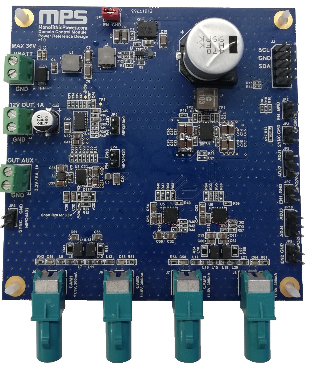
Domain Control Module - Automotive Power Stage for ADAS Applications
This reference design serves as a guideline to help users design a power supply for ADAS, using a domain control module as an example
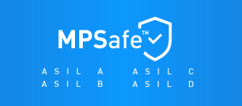
Automotive Safety Integrity Level (ASIL)
The automotive safety integrity level (ASIL) is a set of safety ratings defined in ISO26262, and uses three factors — severity, exposure, and controllability — to determine a grade (from A to D) by asking the following questions:
- Severity: If a failure occurs, what would the consequences look like? Would it affect the driver, passengers, and/or those outside the vehicle? Severity is comprised of the following ratings:
- S1 (light to moderate injury)
- S2 (severe injuries where survival is probable)
- S3 (severe and fatal injuries)
- Exposure: How often is the system going to be exposed to this particular environment or situation? Exposure is comprised of the following ratings:
- E1 (very low)
- E2 (low)
- E3 (medium)
- E4 (high)
- Controllability: If a failure occurs, how easily will those around or operating the vehicle be able to avoid injury and/or damage? Controllability is comprised of the following ratings:
- C1 (easy to control)
- C2 (normal)
- C3 (difficult or uncontrollable)
For example, the exposure level for driving on the highway is considered E4, as this is a common environment for vehicles.
With these three factors combined, the ASIL ratings are simple to determine (see Figure 1).
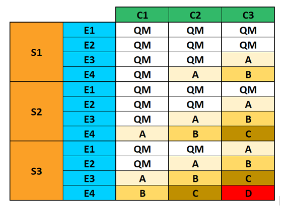
Figure 1: ASIL Requirements
Quality management (QM) is a level at which there are no safety requirements.
ASIL A is the easiest safety level to meet. An ASIL A example would be an unintended start/stop failure during heavy traffic. In this scenario, the exposure is E3 (1% to 10% of the average operating time), the severity is S1 (light-to-moderate injuries with low vehicle speed), and the controllability is C3 (it is difficult to avoid the accident since the objects are so close to each other).
ASIL B covers light-to-moderate conditions, such as when a vehicle involuntarily accelerates on the highway. In this case, the exposure is E4 (more than 10% of average operating time, since cars accelerate in almost every drive cycle), the severity is S3 (an accident with high speed), and the controllability is C1 (the driver can slow down or stop the vehicle by controlling the brake).
ASIL C covers moderate-to-severe conditions. An ASIL C example is if the steering wheel loses function while executing a turn. In this situation, the exposure is E4 (since the steering wheel is frequently used), the severity is S2 (severe injuries with probable survival), and the controllability is C3 (it is difficult for the driver to control the vehicle and avoid an accident).
ASIL D is the most difficult requirement to meet, at the only intersection between S3 (severe and fatal injuries), E4 (high exposure), and C3 (difficult or uncontrollable), such as a brake failure while the vehicle is operating at a high speed. In this scenario, the exposure is E4 (drivers use the braking system in almost every drive cycle), the severity is S3 (critical injuries and uncertain survival), and the controllability is C3 (it is very difficult for a driver to slow down the vehicle and avoid an accident).
MPSafeTM aims to support product use in systems across the entire ASIL spectrum.
MPSafeTM Procedure
MPSafeTM starts with the concept phase and involves experienced safety engineers and IC experts. A proper and adequate starting concept helps to ensure safety audit success, on-time schedules, and well-managed costs.
There are a few basic points that must be addressed when first defining a part. First are the top-level requirements, such as vehicle and system requirements. As discussed earlier, the safety argument always begins at the vehicle/system level. As a result, it is necessary to define certain vehicle/system safety requirements to then define the proper IC requirement. From these requirements it is then possible to address the IC-level requirements, which determine how you define your IC to meet top-level requirements. In other words, the first two questions are typically, “What does the vehicle need?” then, “What are the requirements to meet that need?”
An IC must be designed from the outset to achieve these requirements. To ensure success, additional reviews are conducted throughout the definition and design stage, as a simple copy/paste error could have the potential to cause problems later in the implementation stages.
These IC requirements should be considered throughout the process, as designers hand over the requirements to the application engineer (AE). An open line of communication ensures AEs will avoid mistakes that may not be caught by the designers. While an IC designer knows how to create the part with the detailed requirements, they may not have visibility regarding the overall system. In this instance, the IC designer may not fully understand how implementing the IC could change the system or lead to device failure, depending on the environment. In addition, customers who want to use the part may not know the exact requirements for their design. It is vital that all stakeholders know the ultimate requirements for each part.
Figure 2 shows the MPSafeTM procedure, which includes five functional safety management (FSM) gates, starting with FSM_0 and ending with FSM_4.
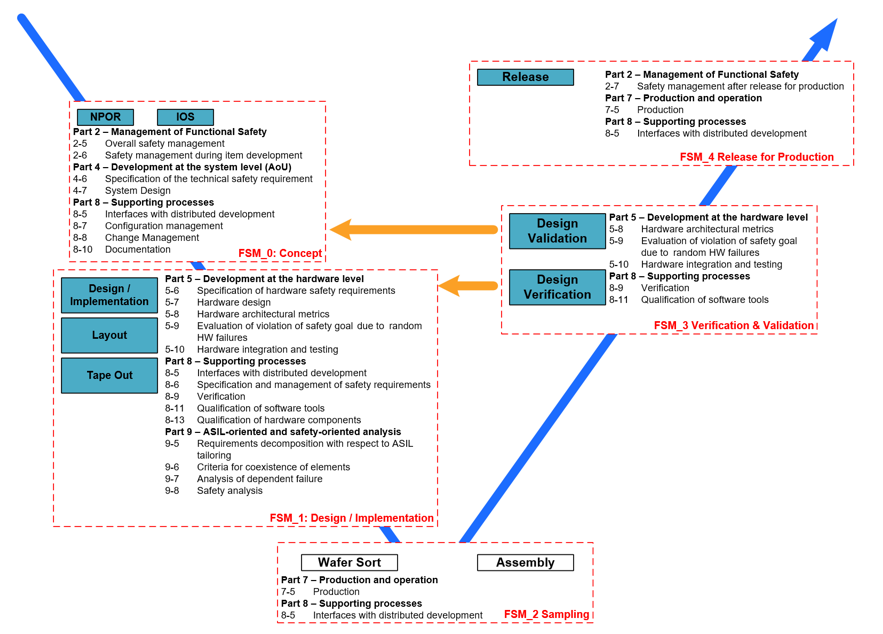
Figure 2: MPSafeTM Procedure
MPSafeTM follows a detailed 5-phase procedure, described below.
FSM_0: Concept
The concept phase operates under the most requirements since it is the stage with the greatest opportunity for human mistakes. The concept stage includes the following:
- Defining the role of each contributor
- Releasing and approving of the safety plan
- Releasing the assumption of the system safety concept
- Managing all documentation with organized processes for each safety case
- Using a third party to confirm safety and development measures
- Reviewing the overall process and safety plan to confirm that a part is ready for design
FSM_1: Design/Implementation
The design phase verifies all functional reports, and includes some of the following steps:
- Defining the IC safety requirements that fulfill the assumed system safety concept
- Performing a dependent failure analysis (DFA) to limit the common failures between IC functions and safety mechanisms
- Performing a quantitative safety analysis (FMEDA) to ensure that the IC design is meeting the system's allocated safety target (PMHF, SPFM, and LFM)
- Confirming all development tools are classified and qualified according to ISO26262
- Performing impact analysis and risk assessment if there are any reusable IPs for the project
- Performing simulations to verify the effectiveness of the diagnostics that are defined in the quantitative safety analysis
- The simulation results, package failure analysis, and qualitative analysis for single-point failures and common failures are performed and verified for safety requirements
- The road test cases are thoroughly defined, as well as the tools intended to create the product
- The third party confirms the review
FSM_2: Sampling
The sample phase procedure is when the part is being sampled. Assembly manufacturers follow MPSafeTM and other guidelines that meet automotive-grade requirements. This information is confirmed by the functional safety manager, and any deviations are immediately reviewed.
FSM_3: Verification & Validation
The tests, verifications, and results for the part are captured and measured during the design verification and validation phase. These tests include electric qualification and reliability qualification, IC characterization, RT functional and electrical verification, and ATE tests. All safety mechanisms and their associated diagnostic coverages must be verified in this phase. If there are any failures or issues, an impact analysis is conducted to address any necessary changes. Then a new sample is created to resolve the problem.
FSM_4: Release for Production
After all of the monitoring and evaluation tests are performed according to MPS standards and the test coverage is evaluated, the product is released to production. The functional safety manager and designated third party confirm all safety-related reviews, as well as all reviews or tests required. All safety arguments must be captured in the safety case and archived for at least 15 years. The product is not be released for production until the safety case is completed and released.
Annual Auditing
Each year, a third-party assessor conducts an annual audit of the MPSafeTM procedures to certify this process and verify that there were no deviations throughout design/production. MPS’s commitment to safety forfeits the use of in-house auditors to ensure that our parts consistently meet safety requirements with an unparalleled level of transparency.
Reducing Human Mistakes
When designing parts, there are two routes for failure: random failure and human mistakes. Random failure recognizes that every electrical component has the capacity for failure, even after rigorous testing and certification. Designers include failsafes and additional safety features to ensure that a random failure does not result in a safety hazard. Human mistakes refer to any typo, miscommunication, or mistake made throughout the design process. In particular, MPSafeTM aims to create a defined protocol to reduce the probability of human mistakes while designers create forward-thinking devices. Because humans inevitably make mistakes, it is important to define a sufficient development process to handle those mistakes.
Human mistakes cover a wide range of mishaps, with consequences ranging from mild to severe. For example, every design requires a simulation to ensure that the design is meeting its intended specifications. If the designer working on the part also conducts the simulation, the designer is less likely to find any issues or discrepancies, as they executed the design process. In this scenario, another engineer should review the simulation to ensure that the IC’s design is satisfactory before the solution is shared. This additional review provides independent involvement to catch any mistakes the designer might have made during the design process. To offer an additional layer of safety for our high-rated solutions, MPS uses a third party to confirm that all products meet the relevant safety requirements.
A more in-depth example of human mistakes could occur when parts are being used in systems beyond what they are tested for. Consider a part that triggers under-voltage protection (UVP) when its voltage drops below 4V. Implementing this part in a system that it was not created for could lower the threshold to 2V instead, which could result in failure since the part cannot fall below 4V without triggering a safety protection.
Unclear safety system goals can also result in mistakes, as aiming for the “highest safety” can increase cost, time-to-market, and complexity while creating parts that don’t meet the system’s specific needs. Because projects can have different reviewing needs at certain stages, safety managers can follow MPSafeTM to determine a project’s exact reviewing needs at any point in the process. For example, multiple scientific reviewers may be needed to review testing samples and data, whereas a schematic may only need one engineer to provide a technical review. This allows each step in the design process to have specified regulations, which can reduce time-to-market.
Conclusion
MPS’s safety-oriented mindset generates system architectures that are not only secure, but customizable and quick to market. The introduction of MPSafeTM helps to avoid human mistakes to ensure that MPS devices meet safety requirements with ease. This procedure enables us to produce automotive products that are ready to meet the increasingly stringent certifications for automotive safety. Future parts will include precision sensors, digitally programmable power converters, motor drivers, voltage monitors and sequencers for high-current solutions, LED drivers, and much more.
_______________________
Did you find this interesting? Get valuable resources straight to your inbox - sent out once per month!
Technical Forum
 Latest activity 19 hours ago
 1 Comment
Latest activity 2 weeks ago
3 Comments
Latest activity 3 weeks ago
2 Comments
1 Comment
Latest activity 2 weeks ago
3 Comments
Latest activity 3 weeks ago
2 Comments
Log in to your account
Create New Account