Advancing the Synchronous Rectifier for New Flyback Converters
DOWNLOAD PDF

Get valuable resources straight to your inbox - sent out once per month
We value your privacy
Introduction
Flyback topology has dominated low-power AC/DC applications for decades due to its simplicity and robustness across a wide operating range. In recent years, synchronous rectifiers (SRs) have replaced the conventional Schottky diode in flyback-based power supplies to significantly improve efficiency.
As the demand for efficiency and power density increases year by year, flyback converters must continue to evolve from conventional flyback topology. Several variants have been successfully implemented in AC/DC applications, such as zero-voltage switching (ZVS) flyback, active-clamp flyback (ACF), and hybrid flyback, which achieves ZVS while also reducing switching loss. This improves efficiency and increases the switching frequency, which are both important for high power density designs.
However, the different operating principles in these emerging flyback variants bring new challenges to SR control. In particular, a synchronous rectifier typically turns on twice in one switching cycle due to the additional switching pulse that achieves zero-voltage switching. The synchronous rectifier’s second turn-on cycle can potentially lead to critical shoot-through for many existing SR controllers. This article proposes a solution to address the risk of critical shoot-through in designing new flyback variants with synchronous rectification.
Types of Variant Flyback Topologies with ZVS
In general, zero-voltage switching in flyback converters is achieved by biasing the magnetizing inductance in the negative polarity, allowing the inductor current to pull the voltage down to zero before the primary switch turns on.
Figure 1 shows the auxiliary winding-based ZVS flyback topology, which is the standard ZVS flyback currently available on the market.

Figure 1: Auxiliary Winding-Based ZVS Flyback Topology
Figure 2 shows the typical operating waveforms of the ZVS flyback controller.
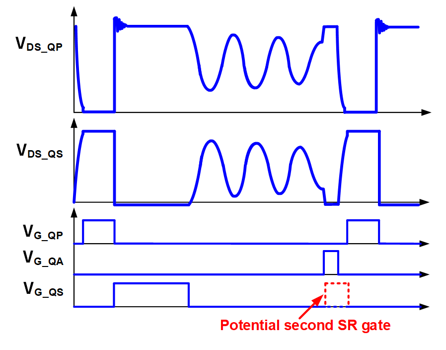
Figure 2: Typical Operating Waveforms of ZVS Flyback Controller
In addition to the primary MOSFET (QP) and SR MOSFET (QS), there is an auxiliary MOSFET (QA) that supports ZVS implementation. Before QP turns on in each switching cycle, QA turns on first for a short period to bias the magnetizing inductance to the negative polarity through the transformer’s auxiliary winding. This process pulls down the QP drain-to-source voltage (VDS_QP) to 0V before QP turns on and zero-voltage switching is achieved.
QA is typically placed on the primary-side ground with QP; thus, QA and QP are controlled by the primary flyback controller to achieve precise synchronization. The SR controller is placed on the secondary-side ground, and determines the turn-on timing based only on the polarity of the QS drain-to-source voltage (VDS_QS). When QP turns off, the magnetizing current is forced to the secondary side, and QS should turn on as soon as VDS_QS becomes negative to efficiently deliver power to the output. When QA turns on, VDS_QS also becomes negative because the transformer’s auxiliary winding and secondary winding share the same polarity.
As a result, it can be difficult for the SR controller to distinguish between QP turning off and QA turning on without a communication path to the primary-side controller. This may lead to a second turn-on event for most existing SR controllers. Since the QA on time tends to be very short and QP turns on immediately following QA, the SR controller continues operating during this minimal on time mode and cannot turn off immediately. In this scenario, shoot-through may occur between the primary side and the secondary side, which poses reliability issues for the power converter.
Figure 3 shows the ACF topology in non-complementary operating mode, which uses discontinuous conduction mode (DCM) to improve light-load efficiency compared to complementary mode.
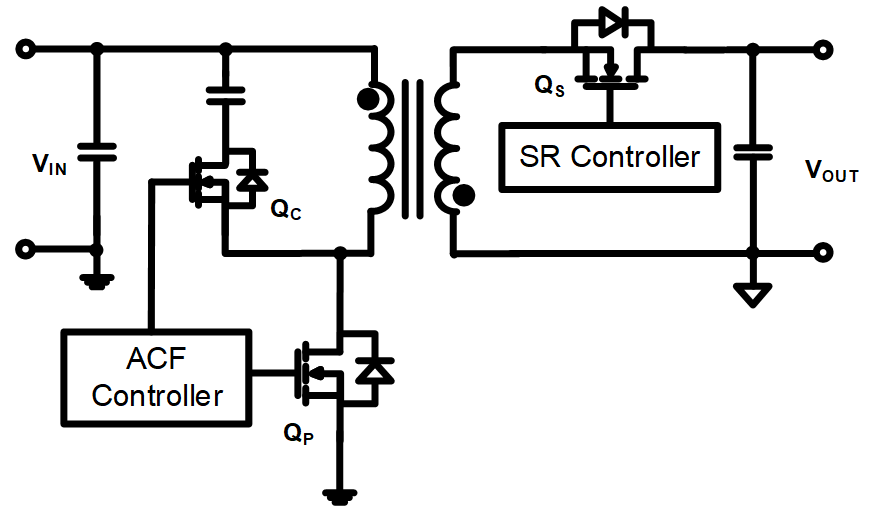
Figure 3: ACF Topology
Figure 4 shows the typical operating waveforms of ACF topology. In this topology, zero-voltage switching is achieved by turning on the clamping MOSFET (QC) for a second time before turning on QP. This also causes a second SR gate with a potential risk for shoot-through.
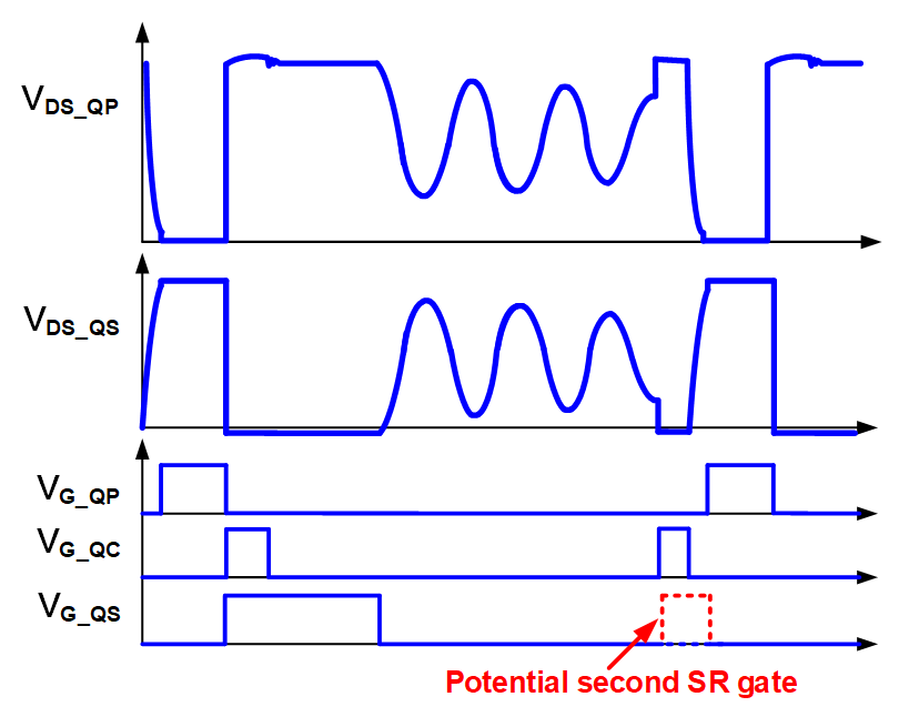
Figure 4: Typical Operating Waveforms of ACF Topology in Non-Complementary Mode
Figure 5 shows hybrid flyback topology in DCM. Hybrid flyback topology utilizes a resonant capacitor to output extra power through the transformer, and also achieves ZVS for both the high-side MOSFET (QH) and low-side MOSFET (QL). Hence, hybrid flyback topology is more suitable for higher power applications compared to conventional flyback topology.
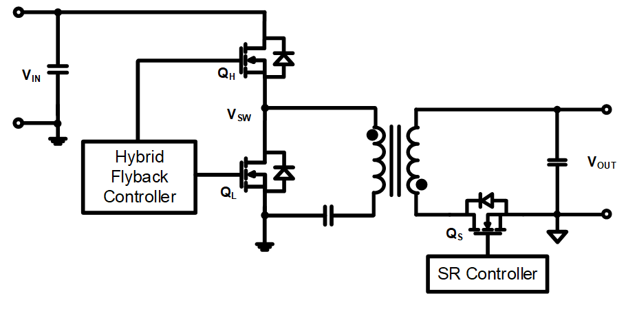
Figure 5: Hybrid Flyback Topology
Figure 6 shows the typical operating waveforms of hybrid flyback topology. Under DCM, QH achieves ZVS by turning on QL for a short period. As a result, hybrid flyback topology can also experience a second SR gate and shoot-through.
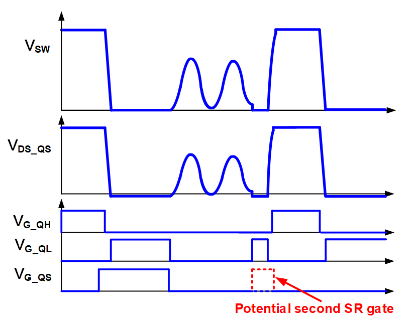
Figure 6: Typical Operating Waveforms of Hybrid Flyback Topology in DCM
Reliable SR Control for ZVS Flyback Topologies
As discussed in the previous section, most existing SR controllers determine the turn-on and turn-off timing by simply comparing the drain-to-source voltage to a certain voltage threshold. This leads to the synchronous rectifier potentially turning on twice in each switching cycle, which can run into conflict with the minimum on time logic and increase the risk of shoot-through. An advanced synchronous rectifier control scheme is required to differentiate between the first and second turn-on occurrence in each switching cycle, as well as to prevent shoot-through under any operating conditions.
The MP6951 is MPS’s latest SR controller that employs an intelligent control scheme to distinguish between turn-on events and manage shoot-through risk. In addition to monitoring the drain-source voltage’s changing polarity, the MP6951 monitors the amplitude and duration of the high-level pulse.
Figure 7 shows that the MP6951 generates a voltage threshold (VP) based on the peak voltage on the drain’s source. In each switching cycle, the drain-to-source voltage is compared to VP in real time. Full turn-on logic is enabled only when the positive pulse lasts longer than the configurable time (tW), and the synchronous rectifier turns on as soon as the drain-source polarity flips.
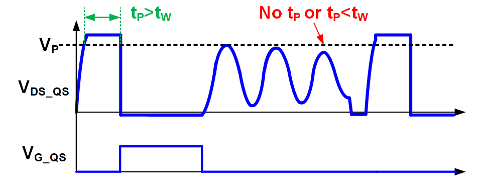
Figure 7: Turn-On Condition for the MP6951
Otherwise, the turn-on logic is disabled or delayed, even when the drain-to-source polarity flips. The synchronous rectifier does not turn on during the second pulse for zero-voltage switching because the drain-to-source voltage does not exceed VP, or the duration of the positive pulse does not exceed tW. Moreover, the MP6951 internally adjusts the tW logic based on various combinations of the input and output voltages. As a result, the synchronous rectifier can always turn on at the most appropriate time.
Figure 8 shows the MP6951’s operating waveforms when using ZVS flyback topology. Generally, the SR gate turns on immediately after the primary MOSFET turns off; however, the SR gate does not turn on when the other switches (including QA, QC, and QL) turn on for zero-voltage switching. Thus, the risk of shoot-through is entirely eliminated.
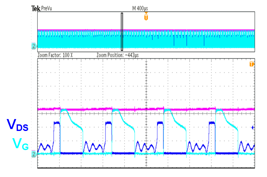
Figure 8: Operating Waveforms of MP6951 in ZVS Flyback Converter
Conclusion
New flyback variants are being quickly developed and implemented to meet the market demand for higher power density and efficiency. SR controllers must also be adapted as more zero-voltage switching variants are being adopted in practical applications. As the leader in the synchronous rectifier market, MPS offers an unmatched level of robust and reliable SR operation with the MP6951. Compared to existing SR controllers, the MP6951 can perfectly match any flyback variant with the key advantage of eliminating shoot-through risk during ZVS operation. Furthermore, the effectiveness of the MP6951’s control scheme among cutting-edge adapter products has been fully verified in theory and production.
_______________________
Did you find this interesting? Get valuable resources straight to your inbox - sent out once per month!
Technical Forum
 Latest activity 4 weeks ago
 1 Comment
Latest activity 4 weeks ago
1 Comment
Latest activity a month ago
8 Comments
1 Comment
Latest activity 4 weeks ago
1 Comment
Latest activity a month ago
8 Comments
Log in to your account
Create New Account