Introducing the MP8017: An Ultra-Small IEEE 802.3af PoE PD Solution

Get valuable resources straight to your inbox - sent out once per month
We value your privacy
Introduction
The development of Power over Ethernet (PoE) devices has resulted in devices with increased functionality, smaller size, and simplified design. This article highlights the MP8017, an ultra-small, IEEE 802.3af-compatible, powered device (PD) solution with a minimal number of external components.
What is PoE?
PoE uses network cables to supply power from the power sourcing equipment (PSE) to the PD. The advantages of PoE over traditional adapter power supply methods include the following:
- Reduced cost
- Simplified installation
- Highly convenient remote control
- Improved compatibility
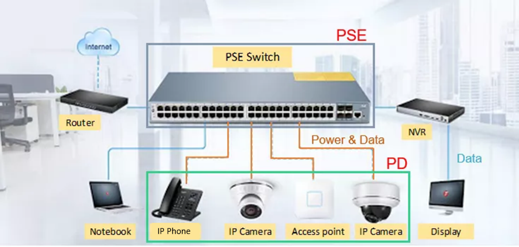
The simple application structure for PoE devices has made them an integral part of products we use on a daily basis (see Figure 1).

Figure 1: PoE Application Structure
Introducing the MP8017
With the extensive application of PoE power supplies, the demand for high-quality power supplies and increasingly complex equipment is rising. MPS committed to PoE application research and developed the MP8017, which significantly improves on traditional solutions. Figure 2 shows a simplified flyback circuit using the MP8017.
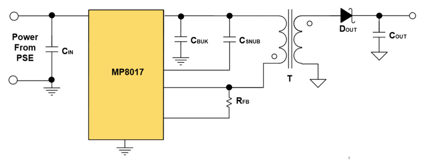
Figure 2: MP8017 PoE Flyback Circuit
Figure 3 shows how the MP8017 optimizes the six modules of the PoE flyback.
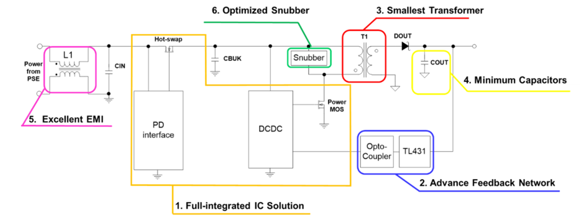
Figure 3: Block Diagream of PoE Flyback Power Supply
Related Content
-
ARTICLE
Designing a Power over Ethernet (PoE) Solution
Learn about the general requirements of PoE
-
WEBINAR

Webinar On-Demand EMC Workshop: Challenges and Early Review of Your Design
Explore the difficulties and challenges of EMI
-
ARTICLE
The Power Over Ethernet (PoE) Powered MP8030
Discover the evolution of the PoE standard
-
VIDEO

Fully Integrated PoE PD Interface: MP8030
DC/DC PoE solution reduces board space and design time
Fully Integrated Solution
To achieve a compact power supply solution, a fully integrated chip contains a PD, DC/DC converter, and hot-swap power MOSFET. Since there are fewer external components, this solution reduces PCB space and shortens design cycles. The MP8017 is available in a ultra-small QFN-19 (3mmx4mm) package (see Figure 4).
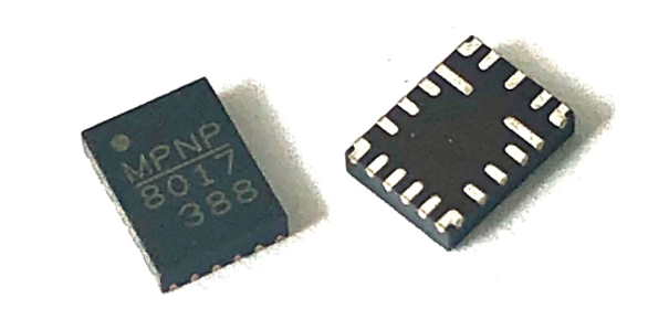
Figure 4: MP8017’s QFN-19 (3mmx4mm) Package
Advanced Feedback Network
A conventional flyback often requires a TL431, optocoupler feedback network, loop compensation, and soft-start circuit. With the development of new flyback solutions, the primary feedback method emerged, which typically includes auxiliary winding.
The MP8017 utilizes an advanced feedback method that does not require auxiliary winding; instead, it directly samples the output voltage (VOUT). This approach has many advantages, including the following:
- Simplified design circuits, including transformers that do not require auxiliary winding
- Reduced transformer cost
- Additional power windings that can be wound on the same core to reduce the impedance and achieve higher efficiency
Figure 5 shows the MP8017’s sampling feedback mode.
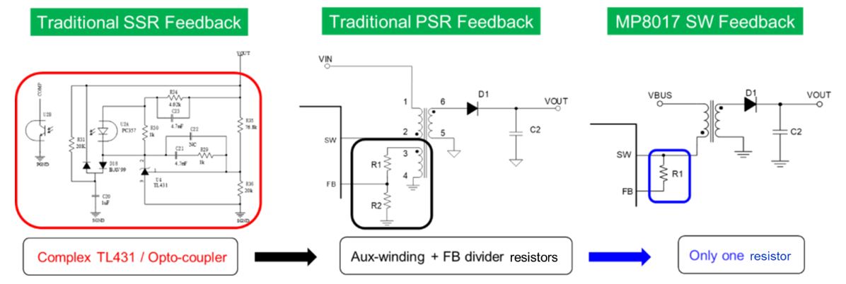
Figure 5: MP8017’s Sampling Feedback Mode
Ultra-Small Transformer
Transformers are generally the most expensive and bulky device in the entire system. The 12W applications on the market today often use EP13 transformers.
In comparison, the MP8017 only requires an EP7 transformer, leading to a significant reduction in both volume and price. The MP8017 has two key design advantages that allow for a smaller and cheaper transformer:
- Auxiliary winding is not required to reduce transformer winding
- Up to a 650kHz switching frequency (fSW) to reduce the number of transformer windings
Figure 6 shows the size difference between EP13 and EP7 transformers. The MP8017’s 12W application adopts an EP7 transformer.
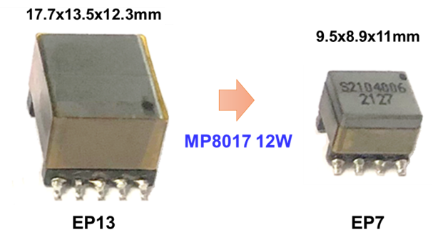
Figure 6: MP8017’s 12W Applications Adopt an EP7 Transformer
Minimum Input and Output Capacitance
The frequency of general PoE devices is typically around 250kHz, which requires electrolytic capacitors to reduce ripples. The MP8017’s frequency (which can reach as high as 650kHz) can greatly reduce the requirements of input and output capacitors. For 12W applications, two ceramic capacitors (0805) are sufficient. The MP8017’s efficient layout reduces current peaks and the ripple caused by ESR or layout resistance.
Excellent EMI Design
Optimizing EMI poses an important challenge for PoE devices in order to pass the EMI standard. Flyback solutions generally require a common-mode (CM) inductor to improve EMI performance. However, the CM inductor is an expensive, large device.
To address these EMI performance challenges, the MP8017 offers the frequency jitter function as well as a smoother SW waveform. The MP8017’s frequency jittering reduces EMI peaks (see Figure 7).
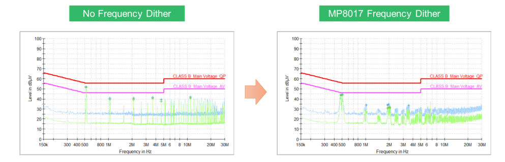
Figure 7: MP8017’s Frequency Jittering Reduces EMI Peaks
Figure 8 shows how the MP8017’s smooth SW waveforms attenuates EMI interference sources.
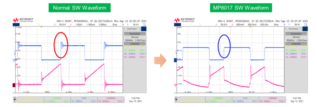
Figure 8: MP8017's Smooth SW Waveforms Attenuates EMI Sources
Optimized Snubber Clamping Circuit
In flyback applications, RCD is typically used as the clamping circuit to reduce SW’s peak voltage and absorb leakage inductance energy. This circuit poses two issues:
- SW produces resonance, which has an adverse impact on EMI.
- After the leakage inductance energy is consumed, system efficiency is negatively impacted.
To mitigate these issues, the MP8017 adopts active-clamp control (see Figure 9).
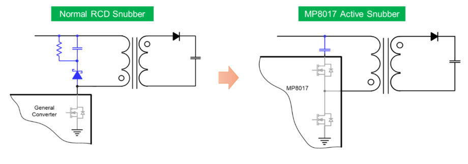
Figure 9: MP8017’s Active-Clamp Circuit
Conclusion
The growing demand for PoE power supplies led to the development of the MP8017. Using the MP8017, designers can effectively optimize the six large modules of the PoE flyback. With features such as high integration, reduced external component count, smaller size, and active-clamp control, this flyback controverter is setting PoE trends in the industry.
_______________________
Did you find this interesting? Get valuable resources straight to your inbox - sent out once per month!
Technical Forum
 Latest activity 5 hours ago
 2 Comments
Latest activity 3 days ago
1 Comment
Latest activity 4 days ago
4 Comments
2 Comments
Latest activity 3 days ago
1 Comment
Latest activity 4 days ago
4 Comments
Log in to your account
Create New Account