Why Microstepping Isn't as Good as You Think

Get valuable resources straight to your inbox - sent out once per month
We value your privacy
Introduction
Stepper motors are often used for positioning since they are cost-effective, easy to drive, and can be used in open-loop systems — meaning that they do not require position feedback like servo motors. Steppers are used in small industrial machines, such as laser engravers, 3D printers, and office equipment like laser printers.
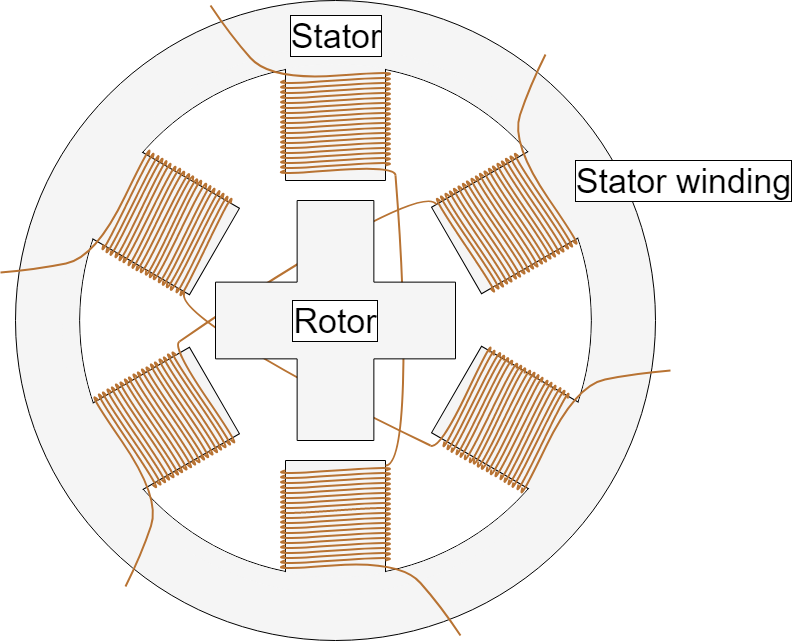
There is a wide array of options when it comes to stepper motors. For industrial applications, 2-phase, hybrid stepper motors with 200 steps per revolution are very common. For these motors, “hybrid” refers to how they use a permanent magnet and a toothed iron rotor (e.g. a variable reluctance motor), and “200 steps” means that the motor moves 1.8° between each step. These steps are a function of the number of teeth on the rotor and stator.
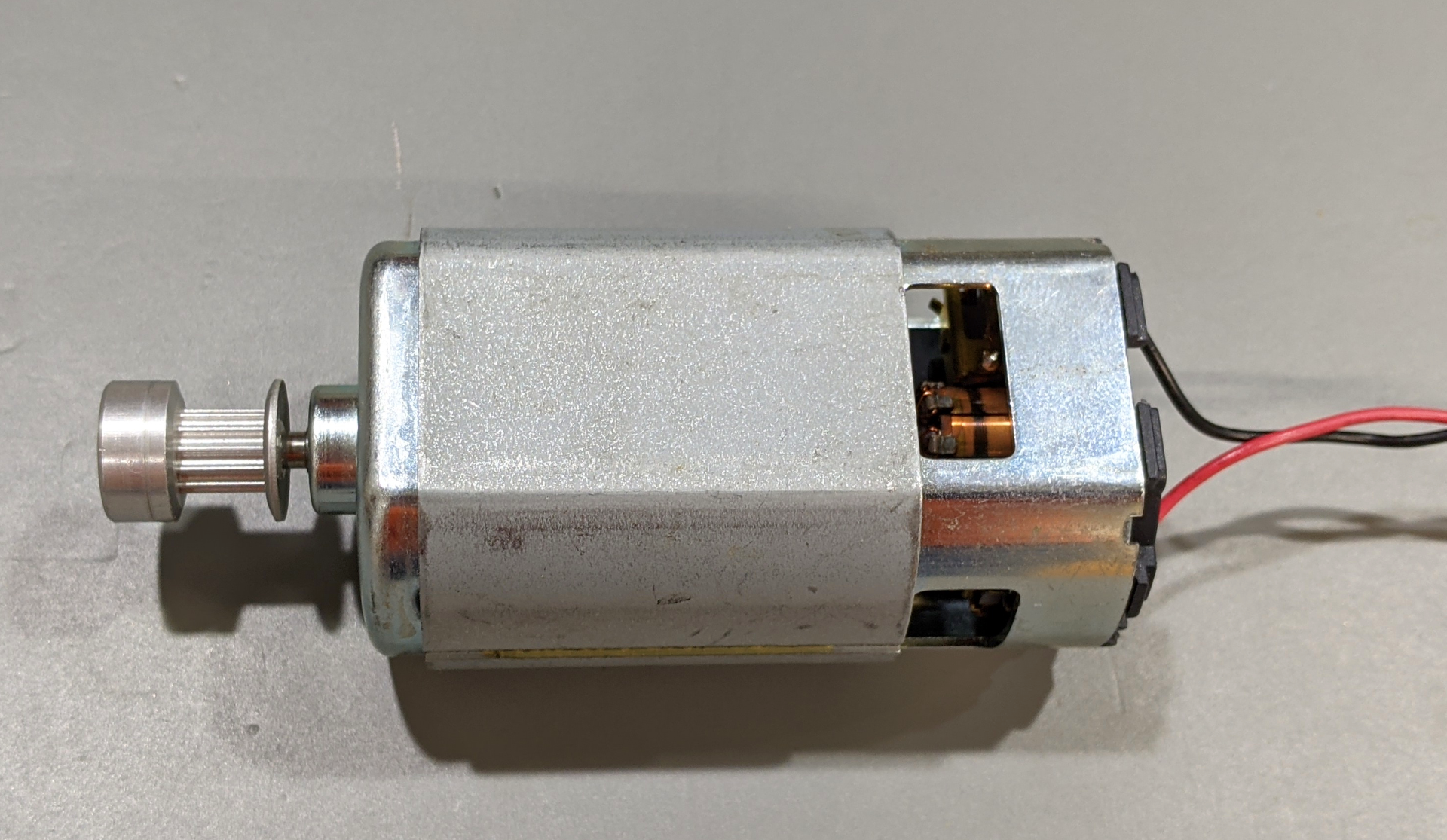
This article will focus on 2-phase hybrid stepper motors since they are the most common. Figure 1 shows a typical 2-phase hybrid motor.
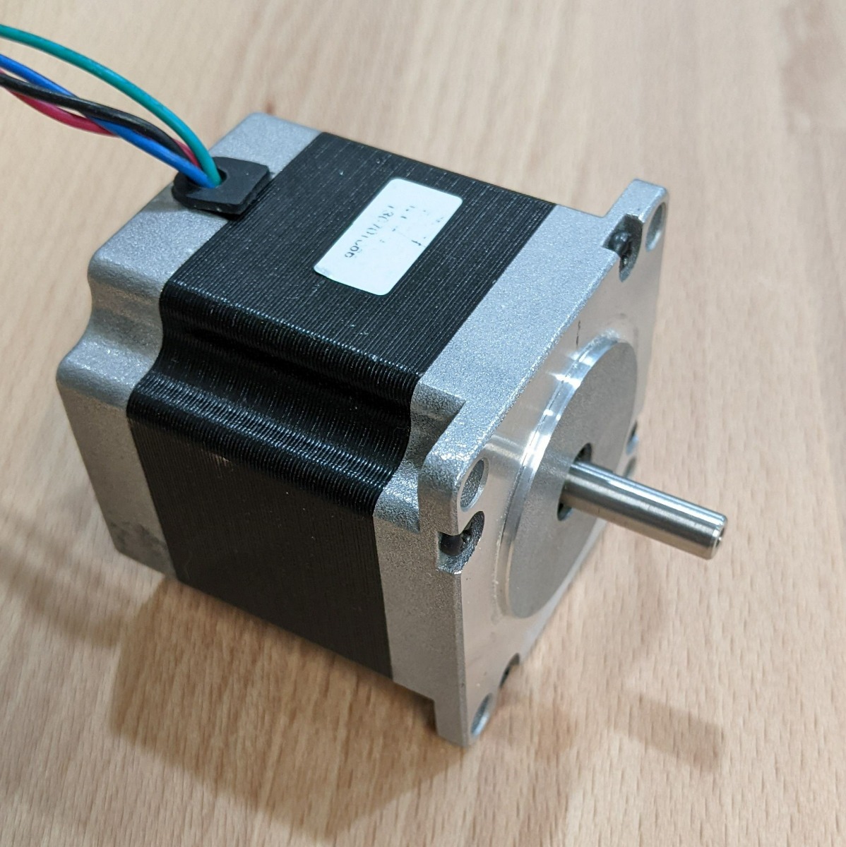
Figure 1: Typical 2-Phase Hybrid Stepper Motor
Microstepping
It is possible to move a stepper motor less than a full step. This process, called microstepping, is accomplished by modulating the current through the windings so that the rotor can be positioned between full steps. Designers can designate almost any size for a microstep, as the step is only limited by the resolution of the digital-to-analog converters (DACs) and amplifiers that drive the winding current. Resolutions of 1/256 — and even 1/1024 — are not uncommon.
In reality, for most mechanical systems, such fine microstepping does not always improve positioning accuracy. A number of additional factors negatively affect performance.
Inherent Errors
There are a few sources of angular errors in microstepping. One is the imperfections of the motor itself — mechanically and magnetically, motors do not have a perfectly sinusoidal current-to-position transfer function. Even if you apply a perfect sine and cosine current to the motor, the motion is not perfectly linear.
Another error source is the stepper motor controller’s current regulation accuracy. Typical stepper ICs are accurate to about 5% of the full-scale current. Additionally, the current regulation matching between the two channels may not be perfect. The result of these inaccuracies reduces positioning accuracy.
For further information about these sort of errors, refer to the application note “Understanding MP6500 Current Control.”
Stepper Motor Torque
Stepper motors are rated with a holding torque. Holding torque is the torque required to pull the motor away from a full-step position, and is also the torque that the motor can generate when moving one full step. After each full step, the teeth are aligned with the smallest magnetic path, which results in a strong torque.
$$Incremental Holding Torque = (Full-Step Holding Torque) \times sin(90° / X)$$Where X is the number of microsteps.
For example, with a 1/8 step, the incremental torque is about 20% of the full-step torque. For a 1/32 step, the incremental torque is only 5% of the full-step torque.
What does this mean for a motion control system? It means that to actually attain the expected position when performing a microstep, the torque load on the motor must be a fraction of the motor’s rated holding torque.
Related Content
-
VIDEO
MP6500 & MP6600: Integrated Bipolar Stepper Motor Drivers
Bipolar stepper motor drivers with internal current sense replace traditional solutions
-
ARTICLE
Stepper Motors Basics: Types, Uses, and Working Principles
Learn about the basics of stepper motors
-
APPLICATION NOTE
Understanding MP6500 Current Control
Discover the many applications of bipolar stepper motors
-
WEBINAR

Webinar On-Demand Motor Drivers Faults and Protections
Take a deep dive on motor driver IC faults and protection
-
ARTICLE
Using Current Regulation in DC Motor Drivers
Using current regulation can allow designers to use a smaller motor driver IC
Lab Measurements
To test position accuracy while microstepping, several experiments were performed. The lab set-up used a first-surface mirror mounted to the stepper motor shaft and a laser. The beam was reflected from the mirror to the opposite end of the lab, a distance of about 9m. The elevation of the laser beam was then measured, and the angle was calculated. Accuracy measurements were limited mostly by the measurement accuracy of the beam height; at ±1mm, this corresponds to an accuracy ±0.006°.
The motor used for the experiments was a typical hybrid motor commonly used in products such as 3D printers. It is a 1.8° bipolar motor, with a rated current of 2.8A and a holding torque of 1.26Nm.
The first experiment measured the accuracy of the motor on its own. It used accurate DC current sources to drive the two phases, and no torque load was applied to the motor shaft. Instead, only the mirror was on the shaft (see Figure 2).
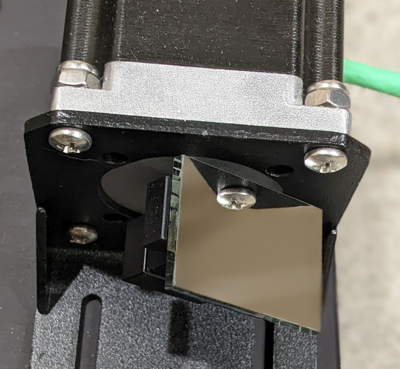
Figure 2: Mirror on Stepper Shaft
The results from this set-up showed small nonlinearities, but in general, angular accuracy was good — it was about ±0.03°, and the motion was monotonic (see Figure 3). That is, the motor never moved in the wrong direction or failed to move. These errors indicate the inherent errors in the motor itself, plus a measurement error. Note that a 1/32 step corresponds to 0.056°.
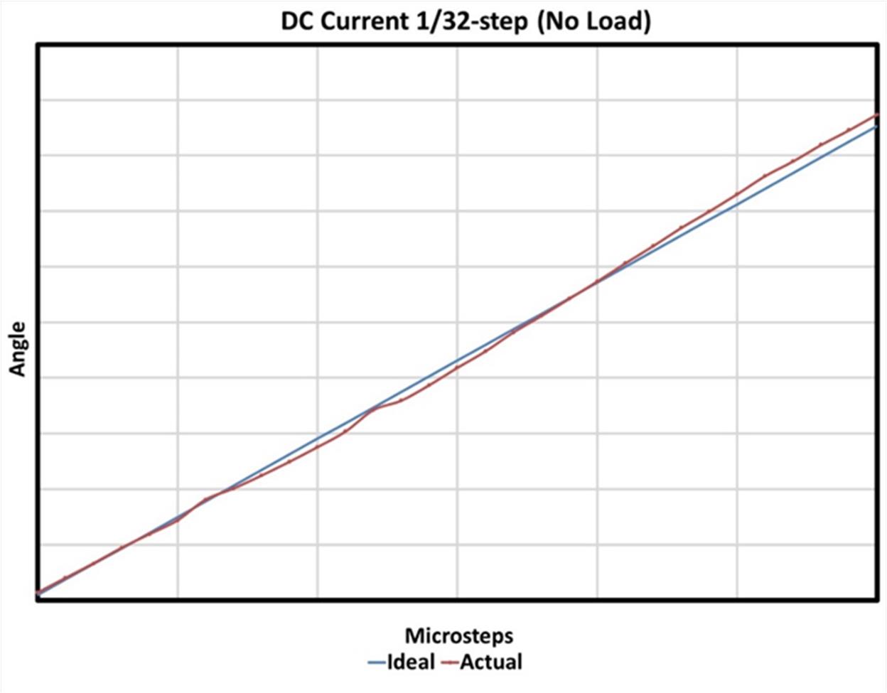
Figure 3: 1/32 Step No-Load Accuracy
Next, the motor was coupled to a magnetic particle brake, which applied a frictional torque load to the motor (see Figure 4).
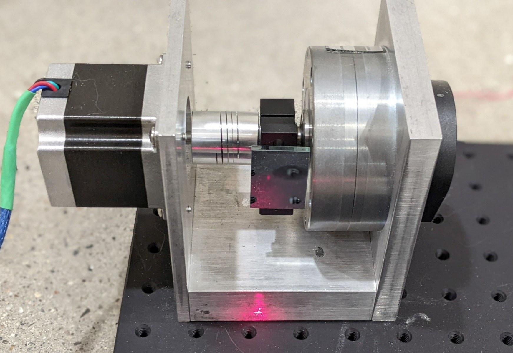
Figure 4: Brake Set-Up
The same measurements were repeated using DC current sources, with approximately 0.1Nm of torque applied to the motor shaft. Figure 5 shows that these results were significantly different, as every other step resulted in no motion.

Figure 5: 1/32 Step with Added Torque
This behavior is in line with the calculated incremental torque for this motor. The incremental torque for a 1/32 microstep is about 5% of the holding torque. In this case, with a holding torque of 1.26Nm, the expected torque generated by one microstep is about 0.06Nm. However, that is not enough to overcome the frictional load, so it takes two microsteps before the torque is high enough to overcome the load.
If we increase torque to 0.9Nm (about 70% of the stall torque) it takes even more microsteps to raise the torque to the point that the motor moves (see Figure 6).
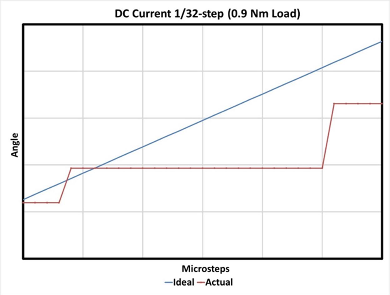
Figure 6: 1/32 Step with 0.9Nm Torque
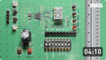
Two similar experiments were performed using MPS’s MP6500, a stepper motor driver IC. The MP6500 uses accurate PWM current regulation, and can operate from a full step to a 1/8 step. Figure 7 shows the MP6500’s block diagram.
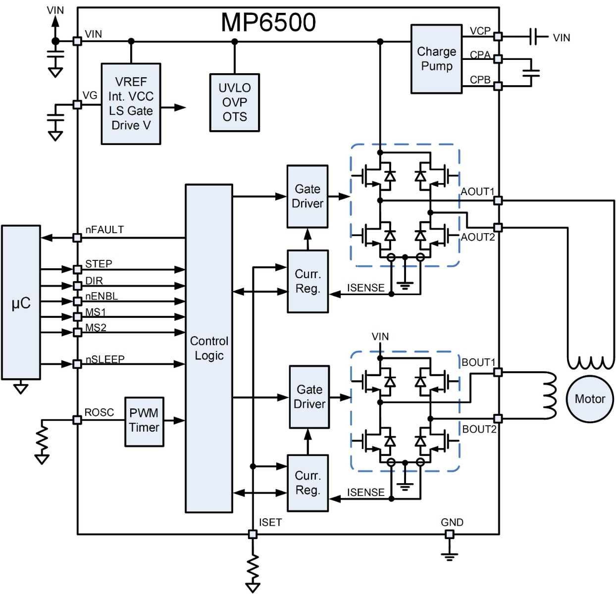
Figure 7: MP6500 Stepper Motor Driver
To test whether the accuracy using a traditional stepper motor driver IC is different than when using DC current sources, the first test was conducted with 0.1Nm torque and 1/8 step mode. The torque produced by 1/8 step is about 20% of a full step, or 0.25Nm — more than the 0.1Nm torque applied. Figure 8 shows the results, which indicates that the actual angle tracked the ideal angle.
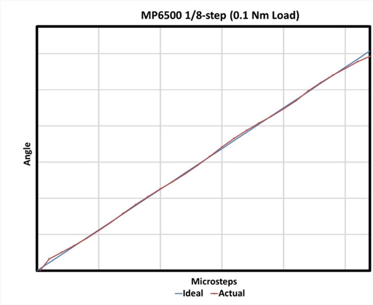
Figure 8: The MP6500 Using a 1/8 Step with 0.1Nm Torque
For the second test, 0.4Nm of torque was applied. This is more than the 1/8 step’s incremental holding torque (0.25Nm). As expected, microsteps are skipped (see Figure 9).
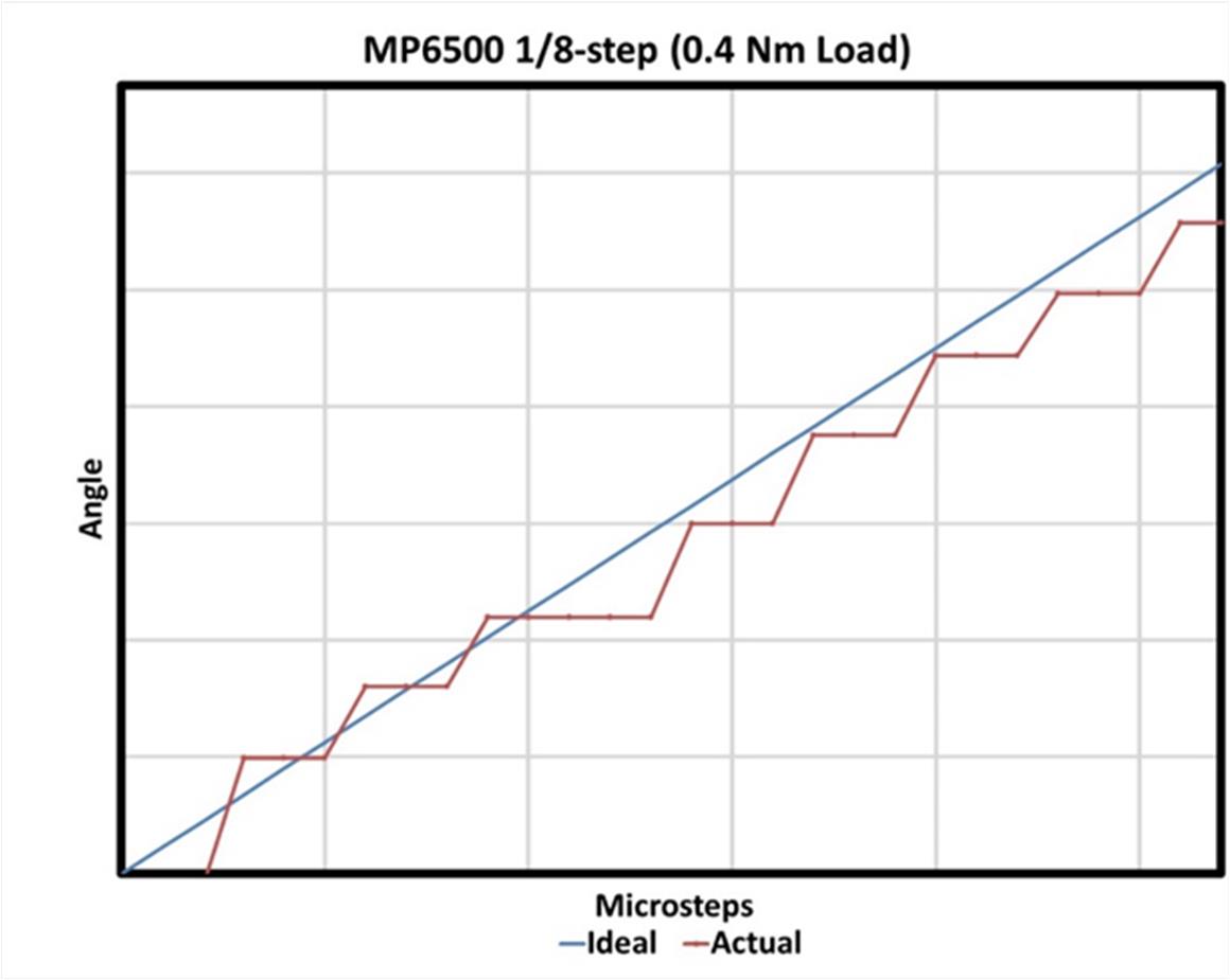
Figure 9: The MP6500 Using a 1/8 Step with 0.4Nm Torque
Mechanical Considerations
To obtain the desired accuracy when microstepping, designers must consider the mechanical system.
There are a few methods to utilize a stepper motor to create linear motion. The first method is to couple the motor to the moving member using a belt and pulley. In this scenario, rotation is translated to a linear motion. The distance moved is a function of the angle of motor movement and the pulley’s diameter.
The second method is to use a leadscrew or ball screw. The stepper motor is directly coupled to the end of the screw, so as the screw rotates, a nut travels in a linear fashion.
In both cases, whether there is actually linear motion as the result of a single microstep depends on the frictional torque. This means that for best accuracy, the frictional torque must be minimized.
For example, many leadscrew and ball screw nuts have some preload adjustability. Preload is a force that is used to prevent backlash, which causes some play in the system. However, increasing the preload decreases backlash, but it also increases the friction. As a result, there is a tradeoff between the backlash and friction.
Conclusion
When designing a motion control system using stepper motors, do not assume that the rated holding torque of the motor still applies when microstepping, as the incremental torque is reduced substantially. This can result in unexpected positioning errors, which were demonstrated by the tests above. In some cases, increasing the microstep resolution does not improve system accuracy.
To overcome these limitations, it is recommended to minimize the torque load on the motor, or to use a motor that has a higher rated holding torque. Oftentimes, the best solution is to design the mechanical system to use larger step increments, and not to rely on fine microstepping. Stepper motor drivers like the MP6500 can use a 1/8-step to provide the same mechanical performance as traditional, costlier microstepping drivers.
_______________________
Did you find this interesting? Get valuable resources straight to your inbox - sent out once per month!
Technical Forum
 Latest activity 7 days ago
 2 Comments
Latest activity a week ago
2 Comments
Latest activity 4 weeks ago
1 Comment
2 Comments
Latest activity a week ago
2 Comments
Latest activity 4 weeks ago
1 Comment
Log in to your account
Create New Account