When Is It Beneficial to Place a Copper Layer Beneath DC/DC Power Supplies?

Get valuable resources straight to your inbox - sent out once per month
We value your privacy
Introduction
Engineers often disagree on whether the inductive bottom of DC/DC power supplies should be laid with copper. The first argument is that laying copper under the inductor produces eddy currents on the ground plane. As a result, the eddy current affects the power inductor’s inductance and increases the system loss, and the ground plane noise impacts other high-speed signals. The second argument is that a complete copper floor reduces EMI and improves heat dissipation.
In this article, we will discuss how inductors are classified, then execute an experiment that lays copper beneath the inductor. Finally, we will explain the benefits of implementing a copper layer before we determine if it is advantageous to place copper beneath DC/DC power supplies.
Inductor Classifications
Before settling the copper layer debate, we must first understand how inductors are typically classified. In short, inductors are divided into three categories, described below.
Unshielded Inductor
An unshielded inductor has a magnetic routing core made up of air, meaning its magnetic lines are entirely exposed to the air without any magnetic shielding.
Semi-Shielded Inductor
A semi-shielded inductor builds on the concept of an unshielded inductor by incorporating magnetic shielding material into the periphery. Due to the conductive material’s small magnetic resistance, the magnetic lines are essentially locked into the material. Only a small part of the magnetic field overflows from the air gap. As a result, this inductor has minimal magnetic leakage externally.
Molded (One-Piece) Inductor
A molded inductor casts the windings and magnetic material at once. This leaves only a small air gap inside, which prevents inductive saturation. Therefore, this type of inductor is largely free of magnetic line overflow.
Figure 1 shows and summarizes all three types of inductors.
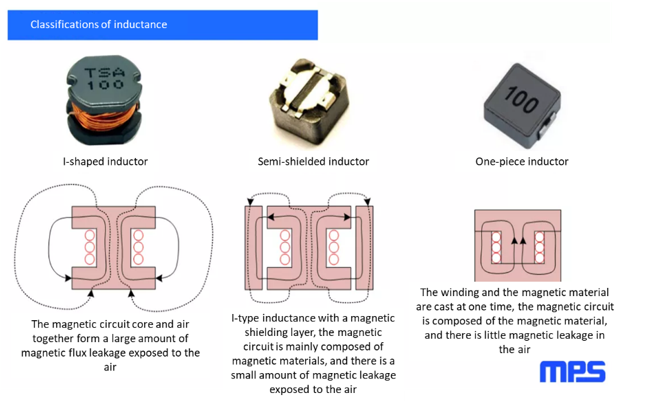
Figure 1: Inductor Classification
Practical Experiment with the MPQ4420
Consider the experiments that were run using the MPQ4420 evaluation board. To simulate placing a copper layer under the inductor, a grounded copper sheet was placed near the inductor. The inductive current ripples were measured to evaluate the effects of laying copper beneath the inductor.
The experimental results showed that the peak inductive current increased by about 8% when the copper was placed close to an unshielded inductor (see Figure 2). When other inductors were used, the inductor current’s peak-to-peak value remained almost constant.
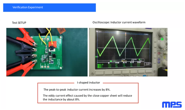
Figure 2: Verification Experiment with the MPQ4420 Evaluation Board
This practical experiment proved that laying copper at the inductor’s bottom only has a small effect for unshielded inductors. The inductance is almost unchanged for either shielded inductor.
Advantages of Laying Copper Beneath an Inductor
When laying copper at the inductor’s bottom, the magnetic field generated by inductors or other high-frequency circuits creates an eddy current at the copper layer. This current weakens the original magnetic lines, similar to how an electromagnetic shield can block the magnetic field’s downward transmission. The overall effect must be considered during EMI testing, since it is important to reduce the high-frequency magnetic field’s impact on other components (see Figure 3). In addition, the EMI filter component and connector can be placed on the back to further optimize EMI performance.
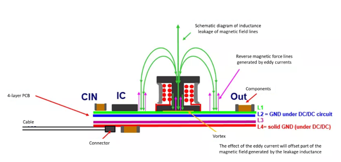
Figure 3: Vortex Effect to Offset High-Frequency Magnetic Field
MPS Inductors
MPS offers both semi-shielded and molded inductors across inductance ranges from 0.33µH to 22µH, with saturation currents between 0.8A and 64A. The MPL-SE series provide semi-shielded inductors — such as the MPL-SE2512-4R7, MPL-SE2512-220, MPL-SE4030-150, and MPL-SE5040-R47 — that use an external magnetic epoxy resin to enhance magnetic characteristics.
The MPL-AL series provides molded inductors with a flat-wire design and low DCR/ACR. These inductors include the MPL-AL4020-R47, MPL-AL4020-2R2, MPL-AL6060-6R8, and MPL-AL6050-R82. Compared to round-wire molded inductors, flat-wire molded inductors achieve higher current ratings.
Conclusion
In conclusion, copper layering is recommended for EMI testing, as it can improve EMI results. In terms of inductance, copper essentially has no effect on shielded inductors, so copper layering is only recommended for shielded inductors.
Given the minimal effect of copper on inductors, it is ultimately up to the engineer to determine whether to use copper according to the application and required specifications.
_______________________
Did you find this interesting? Get valuable resources straight to your inbox - sent out once per month!
Technical Forum
 Latest activity 4 months ago
 2 Comments
Latest activity 9 months ago
3 Comments
Latest activity 11 months ago
5 Comments
2 Comments
Latest activity 9 months ago
3 Comments
Latest activity 11 months ago
5 Comments
Log in to your account
Create New Account