USB Type-C Charging Connectors: Design, Optimization, and Interoperability

Get valuable resources straight to your inbox - sent out once per month
We value your privacy
EU Mandate for the Common Charger
In June 2022, the EU parliament approved a mandate that will require the next generation of portable devices to be compatible with USB Type-C charging connectors. Manufacturers have until fall 2024 to make their products compatible with USB Type-C cables by adding a USB Type-C connector. Affected industries include mobile phones, digital cameras, handheld video game consoles, portable speakers, keyboards, portable navigation devices, earbuds, mice, e-readers, headsets, and headphones. Laptops are also included, though manufacturers do not need to adhere to this mandate until 2026. In 2027, the EU parliament plans to add additional devices to this mandate, then will reconvene every 5 years afterward to discuss other applications.
As this mandate begins to take effect, manufacturers will be required to offer a version of their product without an in-box charging adapter, and they can optionally offer another version with the in-box charger. If a consumer already owns a USB Type-C charging cable and charger, they can save money and reduce e-waste by opting for the version of their product without a new charger. It is estimated that this mandate can prevent up to 22 million pounds of e-waste each year.
This article will discuss USB Type-C connectors — how they work, how they are defined, and their typical applications — while using MPS products to highlight how USB Type-C connectors can be optimized.
Related Content
-
ARTICLE
Battery Charger IC Fundamentals
MPS’s battery charger solutions cover a wide range of high-performance ICs that can complement any battery powered application
-
VIDEO
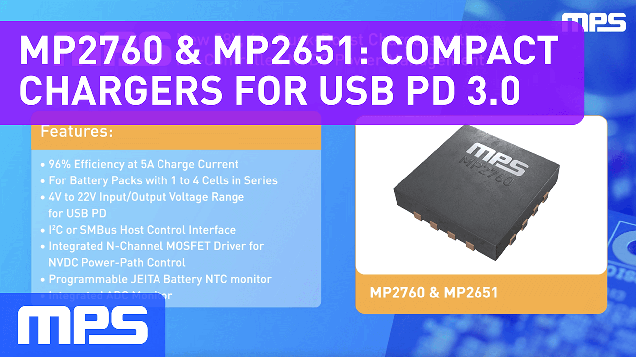
MP2760 & MP2651: Compact Buck-Boost Chargers with Integrated FETs for USB PD 3.0
Buck-boost chargers with I2C-controlled NVDC power management
-
APPLICATION

Power Banks
MPS’s advanced power management solutions offer everything you need to design reliable, efficient, and cost-effective power banks
-
REFERENCE DESIGN
MP2731 USB PD Reference Design
4.5A, NVDC single-cell charger with OTG
USB Type-C Connectors
The USB Type-C (also called USB-C) specification was published in 2014, and these connecters quickly gained popularity due to their advantages over older USB connectors, such as USB Type-A. USB Type-C connectors are reversible, meaning they do not require a particular orientation when going into a port, and they are also smaller than legacy connectors (see Figure 1). In particular, USB Type-C connectors can handle much higher power, which means they can be implemented across a wider range of portable applications.
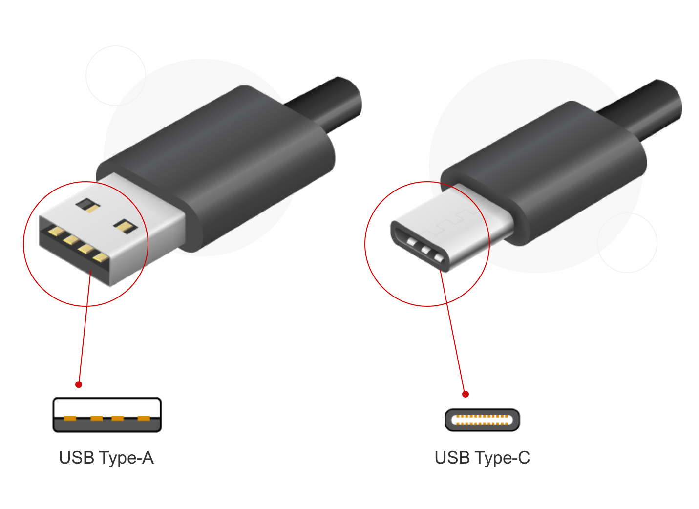
Figure 1: USB Type-A vs. USB Type-C Connectors
USB Type-C Power Detection
USB Type-C connectors have a specific power detection and negotiation interface. Consider when a user plugs a USB Type-C cable into a product. A USB Type-A power supply constantly outputs 5V; in contrast, the USB Type-C power supply is normally off. This is because USB Type-C connectors have a detection function in a separate configuration channel (CC) pin to determine when to turn on after detecting connections on both ends of the cable.
In addition, the CC pin allows for current-level detection and role orientation between the power supply (source) and power consumer (sink). This allows USB Type-C products to maintain compatibility with legacy 5V USB products, while also enabling higher power detection through the use of the USB power delivery (USB PD) protocol, which also utilizes power negotiation on the CC pin.
Figure 2 shows the basics of USB Type-C power detection.
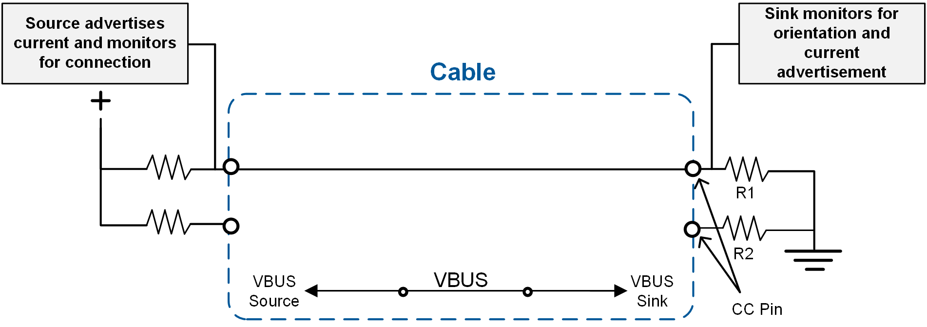
Figure 2: USB Type-C Configuration Channel on the CC Pin
USB Type-C Power Levels
As mentioned earlier, USB Type-C connectors are incredibly powerful, and they support various newer standards, such as USB PD, USB 3.1, and DisplayPort. Older USB connectors can provide upwards of 7.5W in a single direction, but USB Type-C can support single-direction and bidirectional applications up to 15W with standard cables and minimal additional circuitry, as well as applications exceeding 15W with USB PD compatibility.
USB PD in the standard power range (SPR) can support up to 20V at 100W. A recent update to the USB PD specification called extended power range (EPR) can now deliver up to 240W. In addition, USB PD allows for bidirectional power flow, meaning a device can provide or receive power — unlike single-direction connectors, such as a micro-B USB, which can only receive power. This wide power delivery range means that USB Type-C with PD can easily charge both smartphones and laptops. (However, not all USB Type-C implementations support USB PD. This will be discussed in greater detail later in the article.)
Table 1 shows the different power levels for different modes of operation that are compatible with USB Type-C.
Table 1: Power Outputs over USB Type-C Connector
| Mode of Operation with USB Type-C | Nominal Voltage | Max Current | Max Power Output |
| Default USB Power (USB 2.0) | 5V | 500mA | 2.5W |
| Default USB Power (USB 3.2) | 5V | 900mA or 1.5A (single- or dual-lane) | 4.5W or 7.5W |
| Default USB Power (BC1.2) | 5V | 1.5A | 7.5W |
| USB Type-C 1.5A | 5V | 1.5A | 7.5W |
| USB Type-C 3.0A | 5V | 3A | 15W |
| USB PD SPR | Configurable up to 20V | 3A (5A with e-marked cable) | 100W |
| USB PD EPR | Configurable up to 48V | 5A | 240W |
USB Power Delivery (USB PD)
As previously discussed, USB PD can provide up to 240W of power and is capable of bidirectional operation, meaning it can supply or receive power. Non-PD USB Type-C sources can deliver up to 15W of power (5V/3A), while USB PD sources can go above 5V, and thus exceed 15W. Increased power delivery means that USB PD can charge devices much faster than legacy connectors. In addition, USB PD specifies the voltage and current tolerances for both the source and sink.
For products that support USB PD, there are two additional chips required (called PD controllers): one chip in the power supply (source), and a second chip in the portable device (sink). Using these two chips, the product communicates through the cable using the CC lines of each chip. The source communicates the voltage and current that it can support, while the sink (e.g. a speaker or phone) communicates the voltage and current that it requires. The source adjusts its output supply accordingly to ensure that the optimal amount of voltage and current is delivered to the sink. Because these two chips increase costs, USB PD is typically not implemented for applications that can get by with less than 15W of power.
Figure 3 shows USB PD communication.
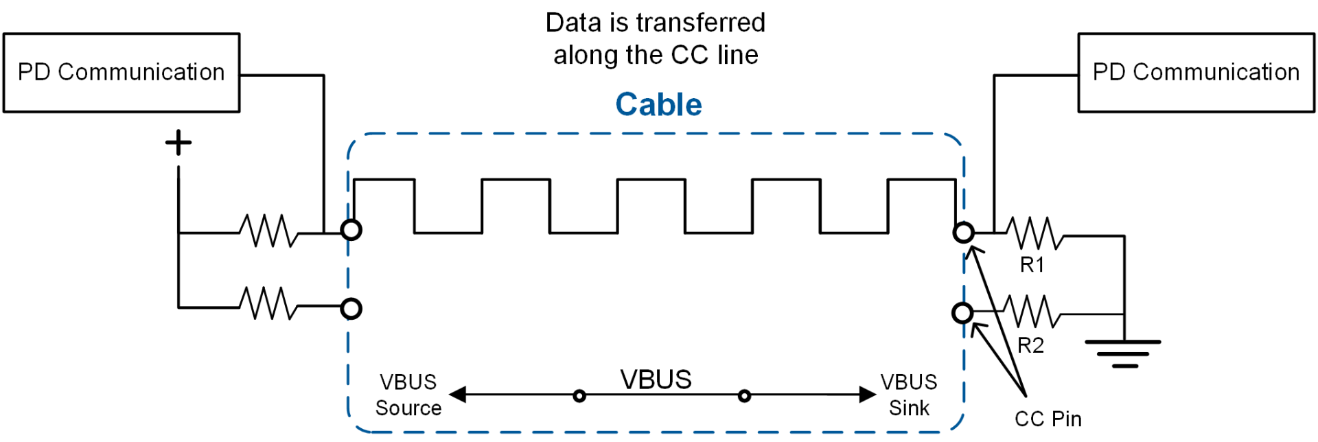
Figure 3: USB PD Communication
The requirement to implement USB PD for applications needing more than 15W is part of the EU mandate. Although some companies have unique protocols to negotiate for higher voltage and power, the new EU mandate states that these other methods are not allowed, in order to maintain interoperability and safety between different charging adapters and devices. Furthermore, using a protocol other than USB PD to increase the voltage above 5V is specifically banned in the USB Type-C specification due to safety and interoperability concerns.
For example, there are certain smartphones that utilize the USB Type-C connector. However, these phones only charge “fast” when plugged into a specific charging adapter with a specific cable because the product does not use USB PD. That means an off-the-shelf USB PD charging adapter may not charge the product quickly, even if its power rating is equivalent to the in-box adapter. This causes user confusion, adds to e-waste, and makes the product’s safety and reliability dependent on a specific manufacturer’s confidential charging protocol.
USB Type-C Connectors: Compliance, Safety, and Optimization
As manufacturers work to implement USB Type-C in their products, it is vital for companies to recognize the difference between an implementation that is physically sufficient versus one that meets USB Type-C specification requirements. A manufacturer can decide whether to submit their product for USB Type-C certification, which means the USB Type-C logo can be used on the product.
Rather than obtain the certification, some manufacturers try to reduce costs by meeting the minimum physical requirement for a USB Type-C connector that can supply or receive power. Although this type of approach is cost-effective, the missing features and functionality can result in safety issues that could damage the device itself or other products connected to it.
Uncertified USB Type-C products can experience a myriad of failures and pose safety concerns, but there are ways to mitigate these issues with robust protections that can protect the cable, source, and sink. Some of these concerns — as well their solutions — are discussed below. Point 1 describes a benefit of certified USB Type-C sinks, while the remaining points describe additional protection and optimization features offered by MPS’s power management ICs.
- Input current detection on the CC pin: Consider USB Type-C implementations without PD compatibility (those below 15W). A USB Type-C source can advertise three current levels: default, 1.5A, and 3A, where default is meant to be backwards compatible with older USB sources (100mA to 1.5A). It is important for the sink to detect the source’s CC pin advertisement to determine how much current can be drawn. A USB Type-C compliant sink can detect the value on the CC pin and adjust its input current limit accordingly to avoid drawing too much current from the source. Once a current limit is set, the sink can dynamically change how much current it draws as the source changes its advertisement.
- BC1.2 and proprietary charger detection: BC1.2 is the standard that defines how a sink can detect the current output capability of a source that either does not have a USB Type-C connector (legacy source) or supplies less than 1.5A. This detection process is executed by using the D+ and D- pins. Proprietary charger detection adds to BC1.2 by allowing the sink to detect common charging adapters.
- Non-compliant legacy cable detection: A legacy cable is defined as having a USB Type-C connector on one end and a different (legacy) USB connector on the other end. To advertise the current level to the sink, legacy USB Type-A cables must implement a 56kΩ pull-up resistor from the CC pin to the VBUS pin on the USB Type-C side. However, there are non-compliant legacy USB Type-C cables that are either missing a pull-up resistor (floating or shorted), or they have a resistor that is the incorrect value. This can lead to incorrect input current limit detection (as described with input current detection using the CC pin), or it can lead to an over-voltage (OV) event on the sink’s CC pin, since the sink’s CC pin may be directly shorted to VBUS. To avoid these issues, the USB Type-C sink device should be able to detect when a non-compliant legacy USB Type-C cable is attached to protect the CC pins.
- Over-voltage protection (OVP) for the VBUS and CC pins: SPR PD charging adapters can go up to 21V, and non-PD charging adapters can go up to 5.5V. Therefore, it is recommended to protect VBUS up to at least 21V in case there is a PD adapter malfunction or a VBUS transient surge occurs. Under normal operating conditions, the CC pin should never experience a high voltage, since CC is either not physically connected to VBUS (e.g. with a USB Type-C cable), or it is connected to VBUS through a 56kΩ resistor (e.g. with a legacy cable). However, since the CC pins are physically located adjacent to the VBUS pins, it is possible for debris in the connector to create a short between them. It is also possible that a non-compliant cable may be attached that shorts VBUS to the CC pin. To protect the CC pins against both use cases, OVP is highly recommended.
- Connector moisture detection: Moisture on the connector can cause corrosion and damage over time, which can lead to shorted or open pins. This is especially common in dual-role port (DRP) or source applications, where the product applies a pull-up voltage or current to the CC pin while advertising source mode (VBus is also enabled during source mode). If the product makes contact with any electrolytic liquid (e.g. water), then the device should be able detect this situation, force the product into sink mode (remove the CC pull-up bias and VBus), and alert the user.
- Connector temperature monitoring: The USB Type-C connector has four VBUS pins and four ground pins in parallel. As the connector gathers debris or wears out over time, some pins may experience open-circuit conditions, which disrupts current flow and results in current crowding in the remaining pins. This additional current heats the connector. To avoid overheating and possible permanent damage, a USB Type-C product should be able to monitor these conditions, alert the user if the connector must be cleaned, and reduce its current consumption to reduce the temperature.
To reduce costs, some manufacturers place two resistors on the sink’s CC pins so that the source turns on 5V when the cable is connected between them (see Figure 4). This configuration is only allowed if the sink does not draw more than the default current, as negotiated over the USB data lines.
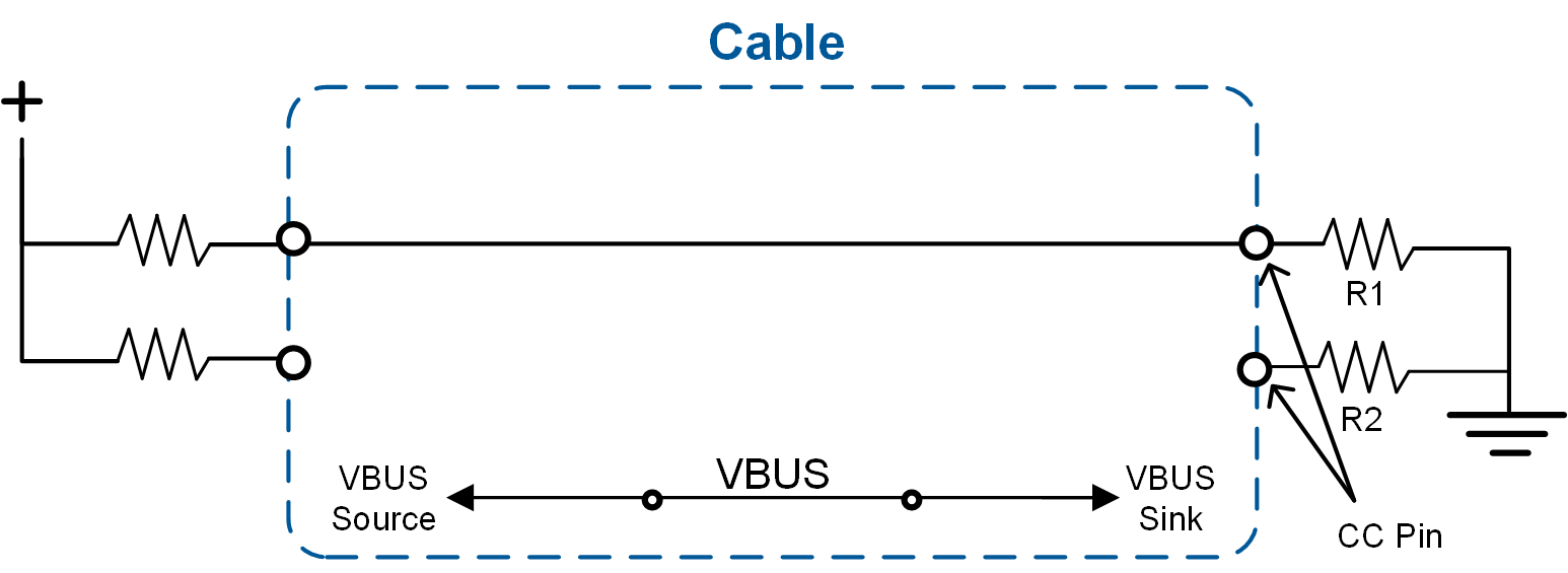
Figure 4: Input Current Detection with Resistors
When resistors are used instead of proper input current detection, the sink does not look at its own CC pin. For example, if a computer has a USB Type-A port, it may only be capable of supplying 500mA. If a sink does not recognize that its source can only supply 500mA, it may try to draw 3A, which would create an over-current (OC) condition and potentially damage the source’s port. Charger ICs in the sink typically also have an input voltage loop, but this only prevents the input voltage from dropping too low. There is no guarantee that the sink charger IC’s minimum input voltage loop will react quickly enough (or be set high enough) to prevent damage to the source. Therefore, this protection should be treated as a backup to CC current detection and input current limiting, instead of the primary protection circuit.
Note that the simple resistor pull-down implementation can be used for sink applications that do not consume more than 1.5A and implement BC1.2 detection (see below).
The USB Type-C specification does not require sinks to implement BC1.2 if they support CC pin detection. However, if the sink does not implement BC1.2, then only 500mA of maximum current can safely be drawn from a USB 2.0 source advertising a default current on the CC pin. Adding BC1.2 to the sink allows for up to 1.5A to be drawn from sources advertising a default current (e.g. legacy sources), which delivers more power, shortens charging time, and leads to a better end user experience.
Use Case for Safety and Optimization
Consider a cable that does not have USB Type-C on both ends. A charger IC could detect when something has been plugged in, analyze the current limit, and determine if the cables are compliant. For USB Type-C to USB Type-C cables, the CC pin passes all the way through the cable — the source supply applies pull-ups, and then the sink (with charger IC) applies pull-downs.
For legacy Type-A to Type-C cables, however, there is a resistor pulling up the CC voltage to VBUS. A few years ago, many of these cables were non-compliant (e.g. they used the wrong resistor or the CC pin was shorted to the input voltage). This led the CC controller or chip to detect a higher current than what existed, meaning that a source with a 500mA current capability would appear to advertise a 3A current capability through the cable. In this scenario, devices such as the MP2722, described in more detail below, can detect if these cables are non-compliant and properly set the input current limit (see Figure 5).
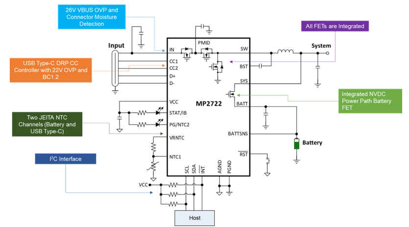
Figure 5: MP2722 Features
A safe and compliant solution has a charger, OVP chip, and CC controller chip (or a chip that detects the CC pin). Some manufacturers forgo the CC pin detection and the OVP chip in the sink to reduce costs. While this implementation electrically functions for a sink, it does not ensure the safety of the attached products. Furthermore, this cannot be used for DRP applications.
MPS Products
MPS has already been setting trends in the field of USB Type-C charging and power management, and offers solutions that cover a wide range of USB applications. Rather than settle for parts that only meet the bare minimum implementation for USB Type-C, our products provide additional benefits for compliance, safety, and functionality.
USB Type-C Applications and MPS Products
A USB Type-C capable power management IC should be selected for the specific application. Generally, these products can be separated into two distinct categories: applications that require ≤15W, and applications that exceed 15W.
For applications ≤15W, products can include smartphones, point-of-sale (POS) systems, speakers, e-cigarettes, headphones, smartwatches, and some tablets. These products do not necessarily require USB PD compatibility, and can simply rely on a CC controller to determine current level and device power role. Not requiring USB PD reduces cost because neither the source nor the sink require an additional PD controller IC. Most products requiring less than 15W use a single-cell battery or multiple cells in parallel. These products can be sink, source, or dual-role power solutions, described below:
- Sink only: For applications that only require a sink, a single-direction, 5V, 15W charger IC can be used to charge the battery and perform sink CC controller operation. The MP2722 is an excellent choice for these applications.
- Source only: Source-only applications include power supplies and car chargers. These applications do not need a battery, so all that is required is a 5V regulator and a source CC controller.
- Dual-role power (DRP): DRP solutions are bidirectional, meaning they can both sink and source power. The MP2722 is a bidirectional, 5V, 15W charger IC that can both charge the battery, as well as provide a 5V output and DRP CC controller.
For applications that require >15W — laptops, power banks, large speakers, power tools, medical devices, and high-end smartphones and tablets — USB PD compatibility is required. These solutions provide DRP, and are typically organized into two main categories:
- Single-cell USB PD: Single-cell (or multiple in parallel) USB PD solutions are typically used in mid- to high-end phones, tablets, and power banks ≤20W. The MP2731 buck charger is designed for implementation in these applications. For more details, see the MP2731 USB PD reference design.
- 2-series to 4-series cell USB PD: USB PD solutions with multiple cells in series are typically used for laptops, tablets, gaming devices, medical equipment and power banks that require more than 20W. These applications require a buck-boost charger, such as the MP2760 or MP2651, which can both be used to create a complete USB PD solution.
MP2722
The MP2722 is a highly integrated, 5V, switch-mode battery charger for Li-ion and Li-polymer batteries. This device provides narrow-voltage DC (NVDC) power path management and is capable of up to a 5A charge current. It is fully compliant with USB Type-C 1.3 and provides an integrated CC DRP controller for bidirectional 15W regulation in source or sink modes. The MP2722 also integrates 26V OVP on the VBUS pin and 22V OVP on the CC pins, and an I2C interface for flexible configurations.
Other 15W DRP USB Type-C implementations require a separate charger IC, DRP CC controller, and an OVP IC for the VBUS and CC pins. The MP2722 integrates all three of these functions into a single chip for maximum area and cost savings (see Figure 6).
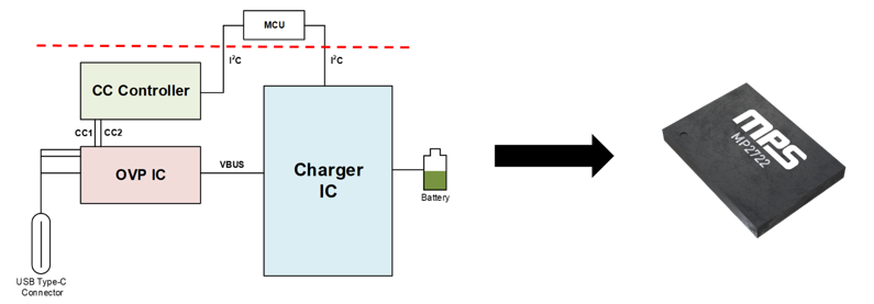
Figure 6: Traditional Solution vs. the MP2722
In addition, the MP2722 supports advanced USB Type-C features, which make it compliant, safe, and highly optimized. These features include connector temperature monitoring, connector moisture detection, non-complaint legacy cable detection, and BC1.2 for optimization with legacy charging adapters. Due to its small solution size and complete USB Type-C feature integration, the MP2722 is ideal for any 1-series cell application looking to implement USB Type-C.
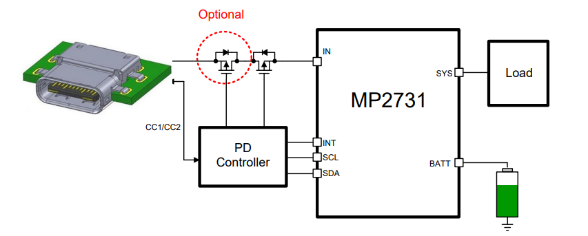
MP2731
The MP2731 is a 15V, 4.5A, switch-mode battery charger with NVDC power path, as well as an integrated analog-to-digital converter (ADC) and I2C interface. A reference design using the MP2731 and external USB PD controller provides a complete solution for USB PD applications while complying with USB PD 3.0 specifications.
This design offers a DRP USB Type-C port that allows bidirectional power and fast charging in sink mode. When a USB input is present, the charger is configured as a sink and charges the battery. If a USB PD sink is connected to the port, the charger acts as a source and supplies a regulated output voltage using the battery as the power source.
The MP2731 PD design can achieve up to 18W of PD fast charging. In addition, the MP2731 integrates an input-blocking FET, which makes using an additional USB PD input FET configuration optional, reducing BOM cost and PCB size. This design is recommended for any 1-series cell applications targeting faster charging through the implementation of USB PD.
MP2760 and MP2651
The MP2760 is a 20V, 6A, buck-boost charger with NVDC power path for battery packs with 1 to 4 cells in series. The device features 4 integrated switching FETs, ADC, and I2C interface for an extremely compact solution. It can operate in boost mode, buck mode, and buck-boost mode, depending on the input and battery voltages; by operating in reverse, this device can power the input from the battery in source mode. The MP2760 battery charger is compliant with USB PD DRP operation across the full range of SPR voltage and current levels.
The MP2651 is pin-to-pin compatible with the MP2760, but is optimized for applications that do not require NVDC power path, such as power banks, power tools, and battery backup products.
Both devices are implemented with the CCG3PA USB PD controller to create a complete USB PD solution (see Figure 7). This solution contains a DRP USB Type-C port for bidirectional operation. If an adapter is inserted, the port can act as a sink and charge the battery. If a sink is inserted, the port can act as a source to power the USB using the battery. For additional flexibility, both parts can be configured via an I2C interface. This design is ideal for applications such as speakers, tablets, medical devices, point-of-sales (POS) systems, drones, and cameras.
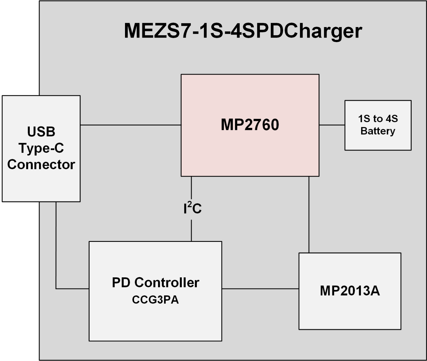
Figure 7: USB PD Solution with the MP2760
Conclusion
USB Type-C connectors (also called USB-C connectors) are versatile, incredibly small compared to older connectors, backwards compatible with older USB standards, and can deliver high power up to 240W. By following the specifications for USB Type-C and USB PD and optimizations discussed in this article, manufacturers help maintain interoperability between products, provide protections that can extend the product’s lifetime, and contribute to the EU’s goal for e-waste reduction.
Although the common charger mandate in the EU is a recent development, MPS has been creating charger ICs and battery management devices designed to cover a wide range of USB Type-C and USB PD applications. Buyers and manufacturers for portable applications can benefit from our extensive portfolio as USB Type-C connectors become more and more common worldwide.
_______________________
Did you find this interesting? Get valuable resources straight to your inbox - sent out once per month!
Technical Forum
 Latest activity 24 hours ago
 1 Comment
Latest activity 2 days ago
1 Comment
Latest activity 4 days ago
1 Comment
1 Comment
Latest activity 2 days ago
1 Comment
Latest activity 4 days ago
1 Comment
Log in to your account
Create New Account