Easy, Cost-Effective Pre-Booster for Automotive Cold Crank Conditions

Get valuable resources straight to your inbox - sent out once per month
We value your privacy
March, 2020 - Start-stop functionality is expected to be featured in more and more new car models from any manufacturer. However, this presents a challenge in automotive electronics design as starting the motor in cold weather can make the battery’s voltage drop as low as 3V. This is called a “cold crank.”
The power stage for most 12V automotive systems consists of a single buck converter that typically regulates the output voltage to 5V or 3.3V. Even if the regulator starts working in low dropout mode, most circuits can be affected by a dip in the input voltage, and may stop functioning.
This article discusses why a pre-boost can be the best solution to this problem, using a typical 5V, 5W to 15W power supply as an example.
Implementing a Pre-Boost
In this scenario, the goal is to keep the output voltage of the power stage at a constant level regardless of the input voltage, while keeping in mind that cold crank only affects the system for a very small proportion of the total working time. This means that a good solution must have minimal impact on cost, efficiency, and EMI.

Figure 1: MPS Pre-Boost Demo Board Response to a Cold Crank Voltage Transient. Test Conditions: VO = 5V, IO = 1.5A
A pre-boost consists of a boost converter that is connected in series before a buck converter. As the name hints, a pre-boost raises the input voltage of the buck converter in case its level drops below a certain threshold. This allows the buck converter to have a steady input voltage and correctly regulate its output to a constant level regardless of transients in the 12V harness. Figure 1 shows an example of a pre-boost, in which the output voltage of the system is immune to perturbations on the input rail.
The beauty of this design is that it takes the input filter inductor and the polarity protection diode, which are typically already used in an automotive application, and uses them for the boost converter. This helps save cost in terms of extra components and board space, while keeping the same efficiency and EMI performance as if the pre-booster were not used.
Figure 2 shows a typical buck converter circuit. In this circuit, the D1 diode protects the system from a reverse polarity battery connection. C1, C2, and L1 form a π (pi) filter for conducted EMI. C3 is the damping capacitor between the filter and the converter. C4, C5, L2, and the buck IC form the buck converter itself.

Figure 2: Simplified Automotive Buck Converter
The pre-boost can be implemented easily by rearranging some components, and adding an asynchronous boost converter and a protection diode (see Figure 3).
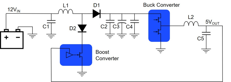
Figure 3: Simplified Automotive Buck Converter with a Pre-Boost
In this configuration, D1 serves as the asynchronous rectifier in the boost converter, and L1 is the boost inductor. C1 and C2 are its input and output capacitors, respectively, while C3 acts as a buffer to hold the voltage for a brief time while the boost starts working in the event of a cold crank. D2 is added to protect the boost IC from reverse-polarity battery connection, and it does not affect efficiency as it only conducts during cold crank. Polarity protection and filtering capability are also maintained.
The MPQ3426 from MPS is a 45V, 6A, AEC-Q100 qualified asynchronous boost converter that can operate from an input voltage as low as 3.2V. With its small 3mmx4mm QFN package and minimal external component requirements, it allows easy implementation of pre-boost while minimizing the impact on cost and performance.
The MPQ3426’s VIN pin is the bias supply for the internal circuitry and should be connected to the buck converter’s output rail. This reduces the losses in the internal LDO, makes the boost IC’s bias supply independent of the system input voltage, and extends the pre-boost operating voltage range to 45V.
On the other hand, since the system always starts with a battery voltage of about 12V, the buck converter turns on and powers the pre-boost, ensuring the input voltage is always higher than 3.2V and increasing its output power capability during cold crank. The lowest transient voltage that the pre-boost can regulate is only limited by the boost IC’s switch current.
Setting the output voltage of the pre-boost between 7.5V and 9.5V ensures that the pre-boost does not start switching during normal condition, but that it will have a fast response when a cold crank situation occurs. Since the pre-boost is not switching in normal condition, it does not create any losses, nor emit EMI. This pre-boost design has been proven in a demo board paired with a buck converter from MPS’s MPQ4430 family of 36V, AEC-Q100 qualified synchronous buck converters (see Figure 4).
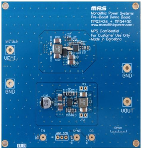
Figure 4: MPS Pre-Boost Demo Board
When designing a pre-boost, special attention must be paid to selecting the inductor and diode. During a cold crank transient, the input voltage is very low but the output power remains the same; therefore, the inductor needs a saturation current high enough that the pre-boost can have good performance during the transient. This saturation current should be greater than the peak inductor current (IPEAK) during cold crank. IPEAK is determined by the maximum input current during cold crank (ILDC) and also by the inductor ripple current (ΔIL), calculated using Equation (1), Equation (2), and Equation (3), respectively.
(1) $$I_{PEAK}= I_{LDC} +{\Delta I_L\over2}$$ (2) $$I_{LDC}= {V_{OUT} ·I_{OUT}\over V_{IN}·^η}$$ (3) $$\Delta I_L={V_{IN}·(V_O-V_{IN})\over V_O·f_{SW}·L}$$For this application, a 2.2µH inductor with a saturation current of 9.2A has been selected.
On the other hand, the diode needs a DC current rating higher than the pre-boost output current during cold crank, which can be about 25% higher than the buck converter’s nominal input current. More importantly, it also requires a peak current rating higher than the peak inductor current (IPEAK) during cold crank.
Automotive applications can have different requirements about the cold-crank voltage profile, some typical ones can be found in Figure 5, with a normal profile, and a severe cold-crank profile. The output power capability of the pre-boost will be very dependent on the minimum voltage level achieved during cold crank as, with lower input voltages, the peak inductor current can be high. Here is a table comparing the maximum output current that the system can supply, versus the lowest voltage during cold-crank.
| Lowest Input Voltage During Cold Crank | Max Output Current at 5V Output Voltage |
| 3.0V | 1.8A |
| 3.5V | 2.5A |
| 4.0V | 3.2A |
| 4.2V | 3.5A |
Table 1: Pre-Boost Demo Board Power Capabilities

Figure 5: Cold Crank Test Voltage Profil
To test the board’s response to a cold crank event, there are homologated automotive voltage transient generators, which come with the voltage profile already programmed. It can also easily be tested with a programmable power supply, which are common in most electronics laboratories. Figure 6 shows a waveform that details the beginning of a cold crank voltage transient in Channel 1, the output voltage of the pre-boost in Channel 2, and the output voltage of the system in Channel 3.
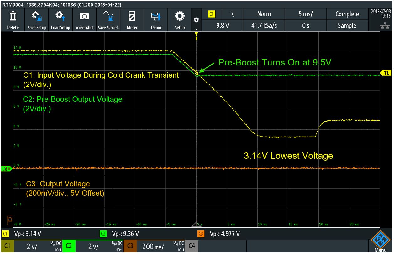
Figure 6: Close-Up to MPS Pre-Boost Demo Board Response to a Cold Crank Voltage Transient. Test Conditions: VO = 5V, IO = 1.5A
Conclusion
The waveform in Channel 3 shows that the output voltage remains constant at 5V without any impact from the cold crank, which takes the input voltage to about 3.2V. Channel 2 shows how the pre-boost quickly reacts to the voltage transient, and regulates the output voltage to 9.5V. This demonstrates that a pre-boost is an excellent solution for automotive systems that require continuous operation during transient voltages.
In higher power applications, the pre-boost can be implemented using a boost controller such as the MPQ3910A, which drives an external transistor and has a higher current capability. Implementing a pre-boost solves cold crank design challenges, saving more cost and space than the few alternatives that exist. This allows for a seamlessly smooth start-stop feature, enhancing the end users’ experience.
_________________________
Did you find this interesting? Get valuable resources straight to your inbox - sent out once per month!
Technical Forum
 Latest activity 2 years ago
 2 Comments
Latest activity 4 months ago
2 Comments
Latest activity 2 years ago
2 Comments
2 Comments
Latest activity 4 months ago
2 Comments
Latest activity 2 years ago
2 Comments
Log in to your account
Create New Account