AN221 - Passing CISPR25-5 with the MPQ4323M-AEC1's Three EMC Filter Components

Get valuable resources straight to your inbox - sent out once per month
We value your privacy
Abstract
This application note demonstrates the electromagnetic compatibility (EMC) benefits of internal, hot-loop multi-layer ceramic capacitors (MLCCs) in a step-down converter module. The MPQ4323M-AEC1 is a step-down converter module that can pass CISPR25 Class 5 with only three external EMC filter components. The results are compared with the MPQ4323C-AEC1, a step-down switching converter module that works with external hot-loop MLCCs. Advantages of the step-down converter module with MLCCs include improved EMC, reduced board space, and a shorter development time.
Introduction
This application note discusses the advantages of the MPQ4323M-AEC1, a 42V load dump tolerant, 3A, low quiescent current (IQ), synchronous step-down converter with integrated hot-loop MLCCs. The PQ4323M-AEC1’s circuit meets the EMC standard CISPR25 Class 5 with only three external EMC filter components. This is possible due to the MPQ4323M-AEC1’s packaging technology that uses internal, 100nF, hot-loop MLCCs on the lead frame. The features of the MPQ4323M-AEC1 are compared to the MPQ4323C-AEC1, a 42V load dump tolerant, 3A, synchronous step-down converter that uses external hot-loop MLCCs.
MPQ4323M-AEC1 "M" With Internal Hot-Loop MLCCs
Internal Hot-Loop MLCCs and Three EMC Filter Components
Figure 1 shows the MPQ4323M-AEC1’s pinout with built-in, 100nF, hot-loop MLCCs in a 0402 package. The VIN and PGND pins are placed on the lead frame near the switching MOSFETs, where the connection between the MLCCs and the MOSFETs is as short as possible.

Figure 1: MPQ4323M-AEC1 with Internal Hot-Loop MLCCs
The hot-loop MLCCs carry high-frequency currents. Parasitic inductance between the MLCCs and MOSFETs generates an unwanted high-frequency voltage, typically called a spike. The spike is a resonance frequency sinewave between 200MHz and 1GHz, depending on the IC and package. A short distance between the MLCCs and MOSFETs reduces the resonance amplitude by reducing parasitic inductance.
The radiated emissions (RE) can be minimized using a short distance between the MLCCs and MOSFETs due to two key factors, described below:
- The lower parasitic inductance reduces the resonance amplitude, resulting in a smaller spike.
- The shorter trace length reduces the trace’s capability to radiate as an antenna.
These two factors combined provide the MPQ4323M-AEC1’s EMC benefits.
Figure 2 shows the schematic of the MPQ4323M-AEC1 to pass CISPR25 Class 5 with only three external EMC filter components.
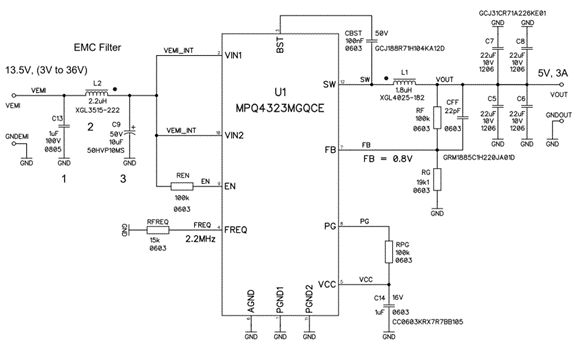
Figure 2: MPQ4323M-AEC1 with Three EMC Filter Components
Emissions of the MPQ4323M-AEC1's Three EMC Components
The MPQ4323M-AEC1’s ability to pass CISPR25 Class 5 with only three external EMC components marks a significant reduction in the BOM compared to a standard step-down converter.
Conducted Emissions of the MPQ4323M-AEC1 "M" with Three EMC Components
Figure 3 shows the conducted emissions (CE) of the fundamental switching frequency (fSW) at 2.2MHz and the corresponding harmonics. The FM radio band has less radiation, with a large margin to the limits. The gray curve is the noise level of the test equipment when the MPQ4323M-AEC1 is powered off under no radiation.

Figure 3: CE Ground Measurement of the MPQ4323M-AEC1 with Three EMC Components
Figure 4 shows the CE on the power supply line, such as the ground CE measurement. The ability to pass the lowest frequencies at 150kHz depends on the low-frequency EMC filter, C13 and C9, and the 2.2µH inductance (L2). Typically, a 22µF capacitance is used to reduce C9 in this circuit to 10µF for lower BOM costs.
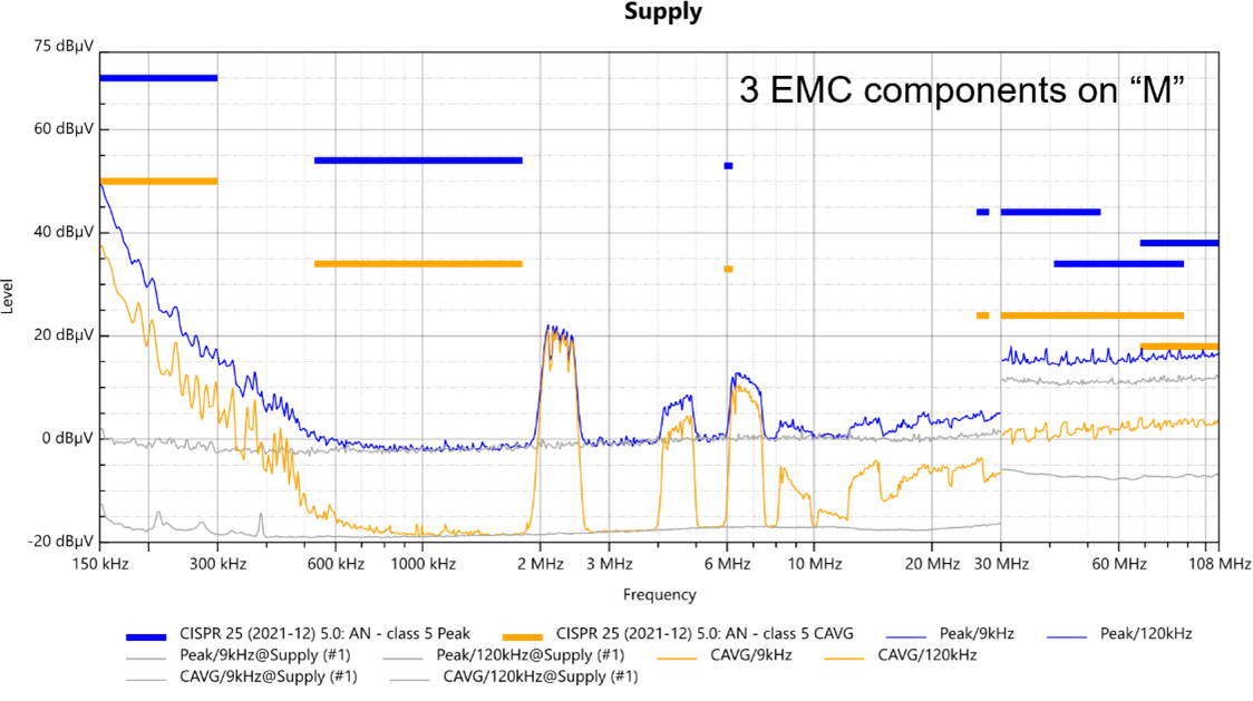
Figure 4: CE Supply Measurement of the MPQ4323M-AEC1 with Three EMC Components
Monopole Radiated Emissions of the MPQ4323M-AEC1 "M" with Three EMC Components
Figure 5 shows the monopole RE measurement using the ground-plane antenna, with a sufficient distance to the limit lines. The monopole measurement is often distorted by the switching inductance.
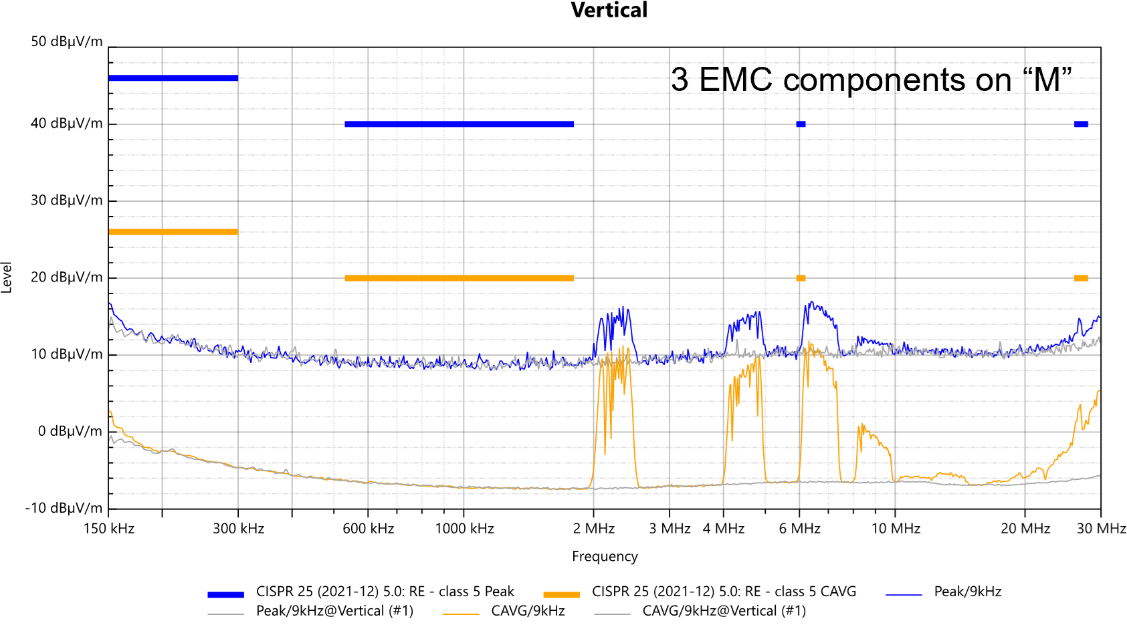
Figure 5: Monopole RE Measurement of the MPQ4323M-AEC1 with Three EMC Components
The EMC filter inductance (L2) has a flat package with a height of 1.5mm. A flat package is recommended as it radiates with less vertical energy. The switching inductor (L1) has a package height of 2.5mm. If available, it is recommended to also choose a flat package for the inductor to pass the vertical monopole RE measurement.
Biconical Radiated Emissions of the MPQ4323M-AEC1 “M” with Three EMC Components
Figure 6 shows the horizontal RE biconical antenna measurement. The antenna polarization is sensitive to RE from the 2-meter power supply harness, which is orientated horizontally flat in parallel to the antenna. This 2-meter harness has typical resonances at 90MHz and 160MHz. Increasing or decreasing the harness length of both peaks changes the frequency. The harness self-resonances can be stimulated by a small noise signal generated from the device under test (DUT).
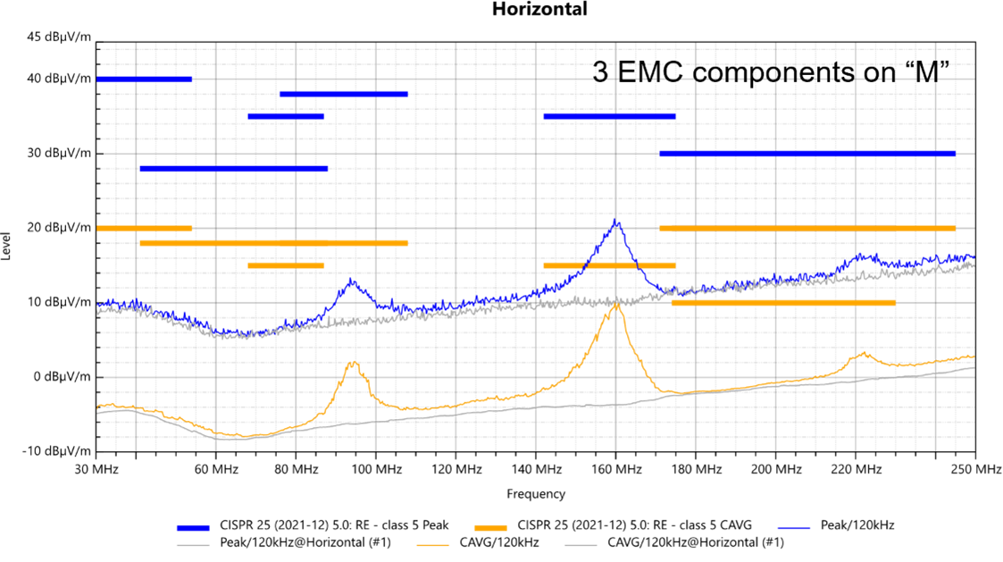
Figure 6: Horizontal RE Biconical Antenna Measurement of the MPQ4323M-AEC1 with Three EMC Components
Figure 7 shows the vertical RE biconical antenna measurement, where the vertical antenna polarization is not sensitive to RE generated on the harness.
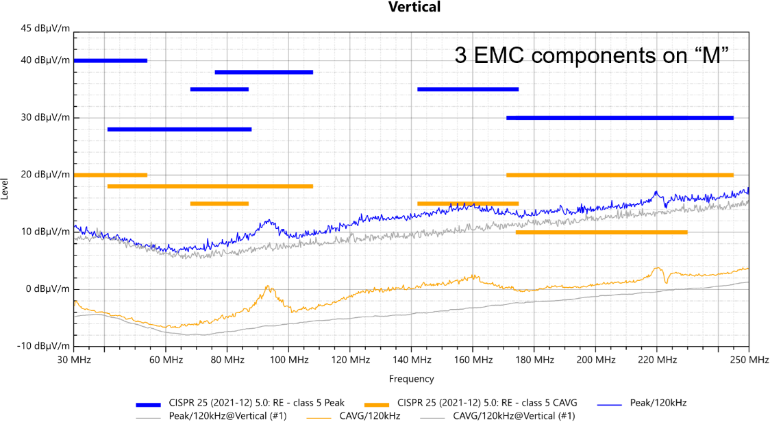
Figure 7: Vertical RE Biconical Antenna Measurement of the MPQ4323M-AEC1 with Three EMC Components
Log Periodic Radiated Emissions of the MPQ4323M-AEC1 “M” with Three EMC Components
Figure 8 shows a RE peak at 860MHz. The switch node provides a stimulus for RE in the EMC filter network and in the hot loop. The MPQ4323M-AEC1 responds with a resonance at 860MHz. Adding more EMC filter components can reduce this 860MHz peak.
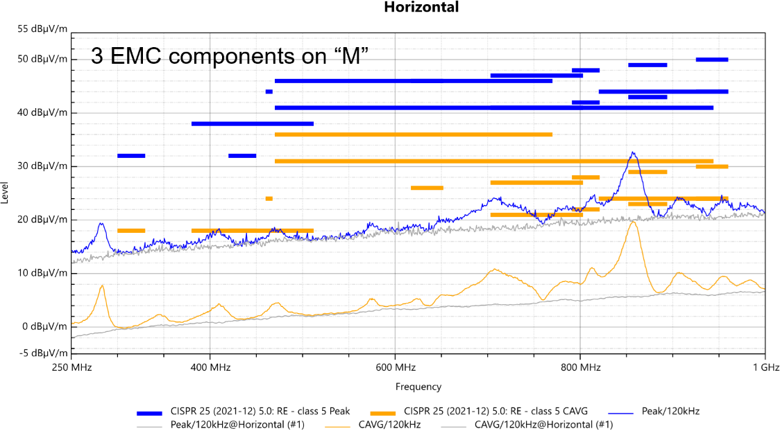
Figure 8: Horizontal RE Log Periodic Measurement of the MPQ4323M-AEC1 with Three EMC Components
Figure 9 shows a RE peak at 800MHz, which is below the limits.
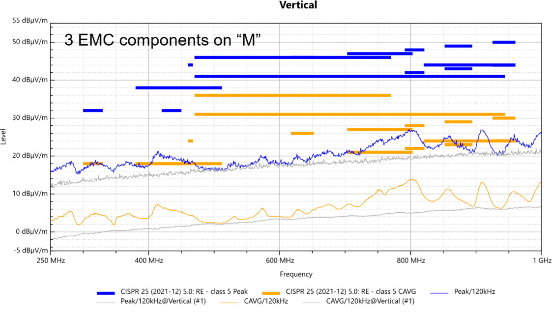
Figure 9: Vertical RE Log Periodic Measurement of the MPQ4323M-AEC1 for Three EMC Components
Horn Radiated Emissions of the MPQ4323M-AEC1 “M” for Three EMC Components
Figure 10 shows the RE measurement with a horizontal polarized horn antenna.
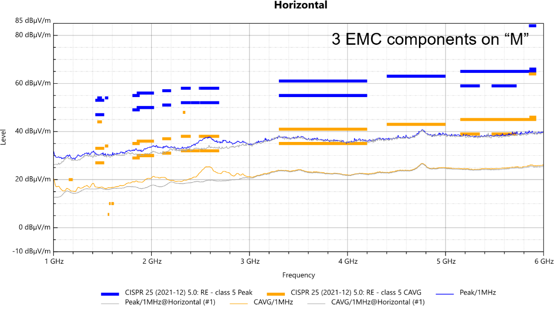
Figure 10: Horn Horizontal RE Measurement of the MPQ4323M-AEC1 for Three EMC Components
Figure 11 shows the RE measurement with a vertical polarized horn antenna, which follows the gray curve of the test equipment noise floor.
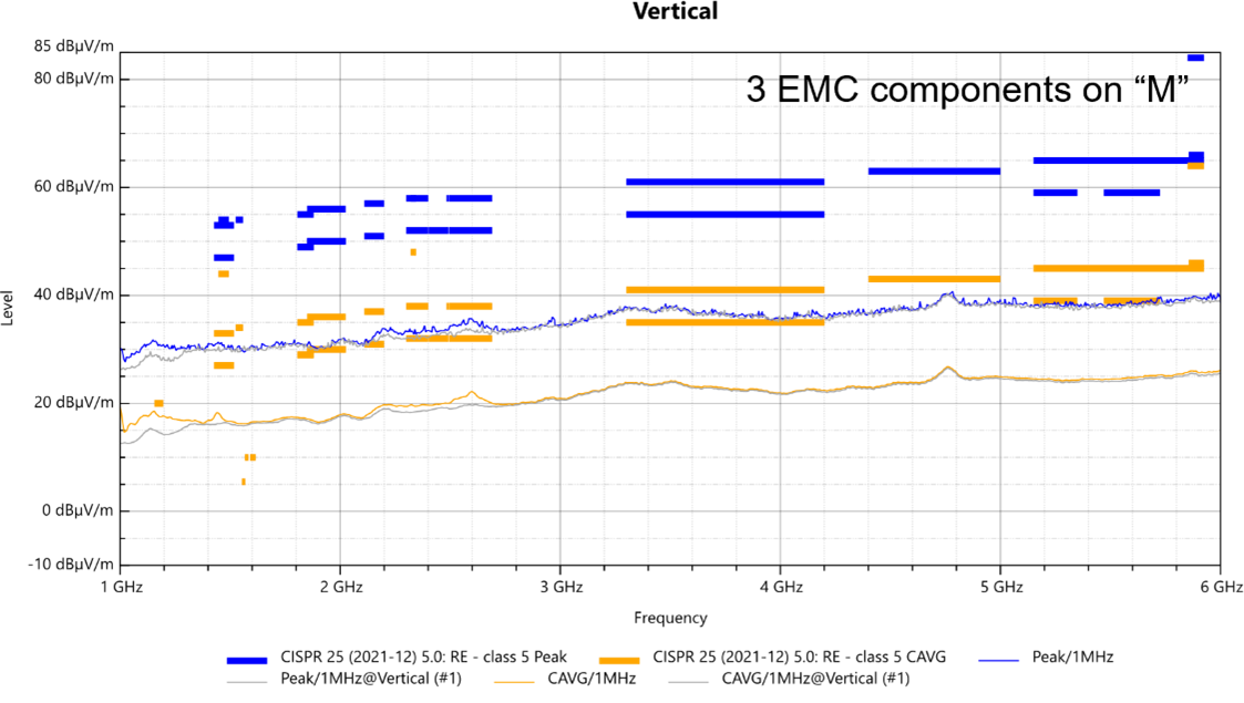
Figure 11: Horn Vertical RE Measurement of the MPQ4323M-AEC1 for Three EMC Components
MPQ4323C-AEC1 "C" with External Hot-Loop MLCCs
The MPQ4323C-AEC1 has the same silicon as the MPQ4323M-AEC1 but uses external, 100nF, hot-loop MLCCs. Compared to the MPQ4323M-AEC1’s QFN-12L (3.5mmx3.5mm) package, the MPQ4323C-AEC1 is available in three different packages.
The MPQ4323C-AEC1 requires 7 external EMC components to meet CISPR25 Class 5 and achieve comparable performance to the MPQ4323M-AEC1 that works with three external EMC components.
Figure 12 shows the MPQ4323C-AEC1 with 7 EMC components under the same conditions as the MPQ4323M-AEC1 circuit in Figure 2.
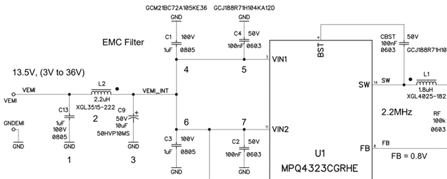
Figure 12: MPQ4323C-AEC1 with 7 EMC Components
Comparison of "M" with 3 EMC Components and "C" with 7 EMC Components
This section shows the advantages of the MPQ4323M-AEC1 “M” with three EMC components compared to the standard MPQ4323C-AEC1 “C” with 7 EMC components.
Radiated Emissions of "M" with 3 EMC Components vs. "C" with 7 Components
Figure 13 shows the horizontal log periodic RE measurement of the MPQ4232M-AEC1 with three EMC components.
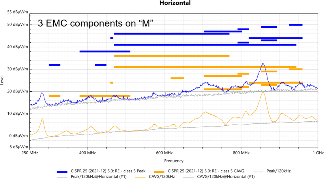
Figure 13: Horizontal Log Periodic RE Measurement of the MPQ4323M-AEC1 for Three EMC Components
Figure 14 shows the horizontal log periodic RE measurement of the MPQ4323C-AEC1 with 7 EMC components.
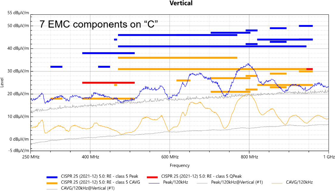
Figure 14: Horizontal Log Periodic RE Measurement of the MPQ4323C-AEC1 for 7 EMC Components
The amplitudes are close to the limits in the direct comparison of the MPQ4232M-AEC1 and MPQ4323C-AEC1 in Figure 13 and Figure 14, respectively. The MPQ4323M-AEC1 “M” with three EMC components performs better than the standard MPQ4323C-AEC1 “C” with 7 EMC components.
To reduce RE from 600MHz to 900MHz, a ferrite bead can be used in both the designs for the MPQ4232M-AEC1 and MPQ4323C-AEC1. However, to achieve the goal of using minimal components to meet CISPR25 Class 5, this is an easier task with the MPQ4323M-AEC1 compared to the MPQ4323C-AEC1.
Advantages of the MPQ4323M-AEC1
To meet CISPR25 Class 25, the MPQ4232M-AEC1 only requires an external 1µF MLCC, 2.2µH inductor, 10µF electrolytic capacitor. Compared to the MPQ4323C-AEC1, advantages of the MPQ4232M-AEC1 include reduced board space, easier layout, faster development to pass EMC, and improved EMC performance in the higher frequency ranges.
Comparison of "M" with 10 EMC Components Vs. "C" with 10 EMC Components
Figure 15 shows the CE supply of the MPQ4323C-AEC1 and MPQ4323M-AEC1 with 10 EMC components and ferrite beads. These evaluation boards have a large margin to the CISPR25 Class 5 limits.
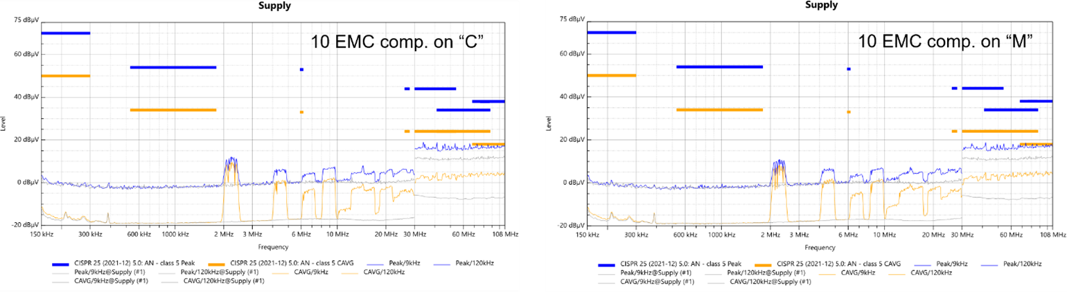
Figure 15: CE Supply Measurement of the MPQ4323C-AEC1 (Left) vs. MPQ4323M-AEC1 (Right) for 10 EMC Components
Figure 16 shows the monopole RE of the MPQ4323C-AEC1 and MPQ4323M-AEC1 with 10 EMC components and ferrite beads, where the fSW harmonics are low.
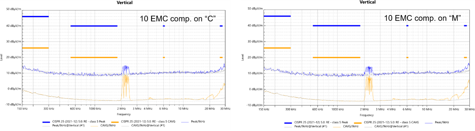
Figure 16: Monopole RE Measurement of the MPQ4323C-AEC1 (Left) and MPQ4323M-AEC1 (Right) for 10 EMC Components
Figure 17 shows the horizontal biconical RE of the MPQ4323C-AEC1 and MPQ4323M-AEC1 with 10 EMC components and ferrite beads. The measurements show the cable resonances of the 2-meter harness.
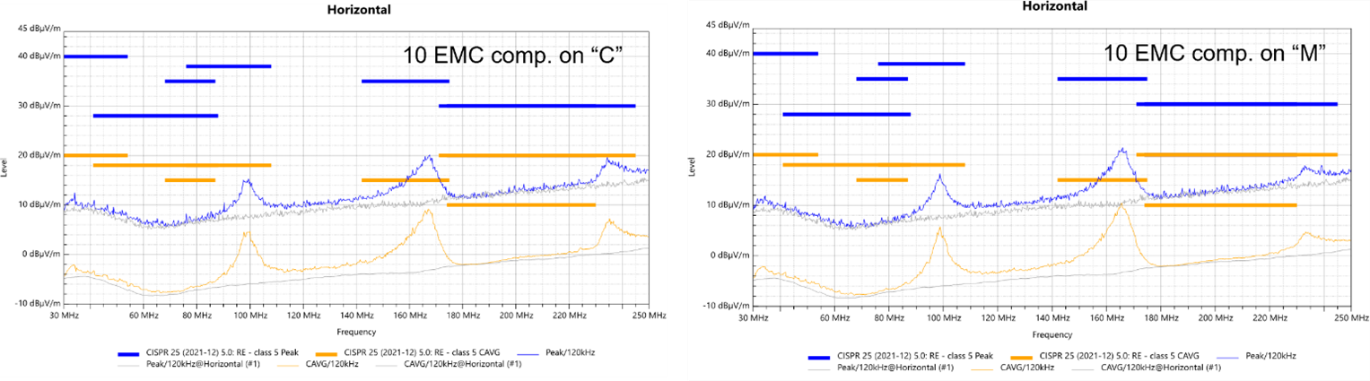
Figure 17: Horizontal Biconical RE Measurement of the MPQ4323C-AEC1 (Left) and MPQ4323M-AEC1 (Right) for 10 EMC Components
Figure 18 shows the vertical biconical RE of the MPQ4323C-AEC1 and MPQ4323M-AEC1 with 10 EMC components and ferrite beads. The harness resonance is attenuated due to vertical antenna polarization.
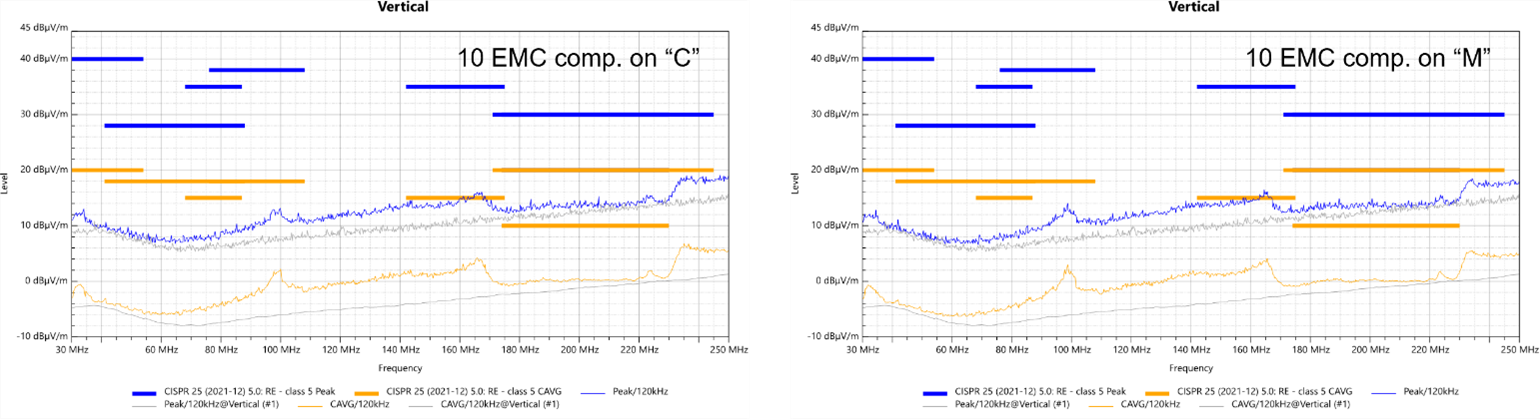
Figure 18: Vertical Biconical RE Measurement of the MPQ4323C-AEC1 (Left) and MPQ4323M-AEC1 (Right) for 10 EMC Components
Figure 19 shows the horizontal log periodic RE of the MPQ4323C-AEC1 and MPQ4323M-AEC1 with 10 EMC components and ferrite beads. The MPQ4323M-AEC1 is significantly better than the MPQ4323C-AEC1.
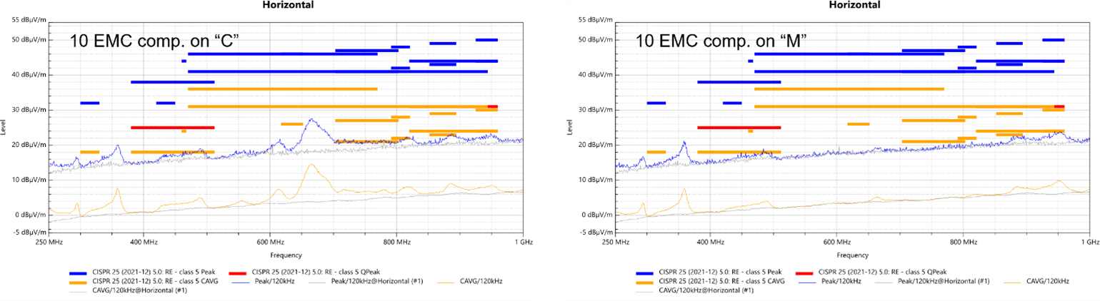
Figure 19: Horizontal Log Periodic RE Measurement of the MPQ4323C-AEC1 (Left) and MPQ4323M-AEC1 (Right) for 10 EMC Components
Figure 20 shows the vertical log periodic RE of the MPQ4323C-AEC1 and MPQ4323M-AEC1 with 10 EMC components and ferrite beads.
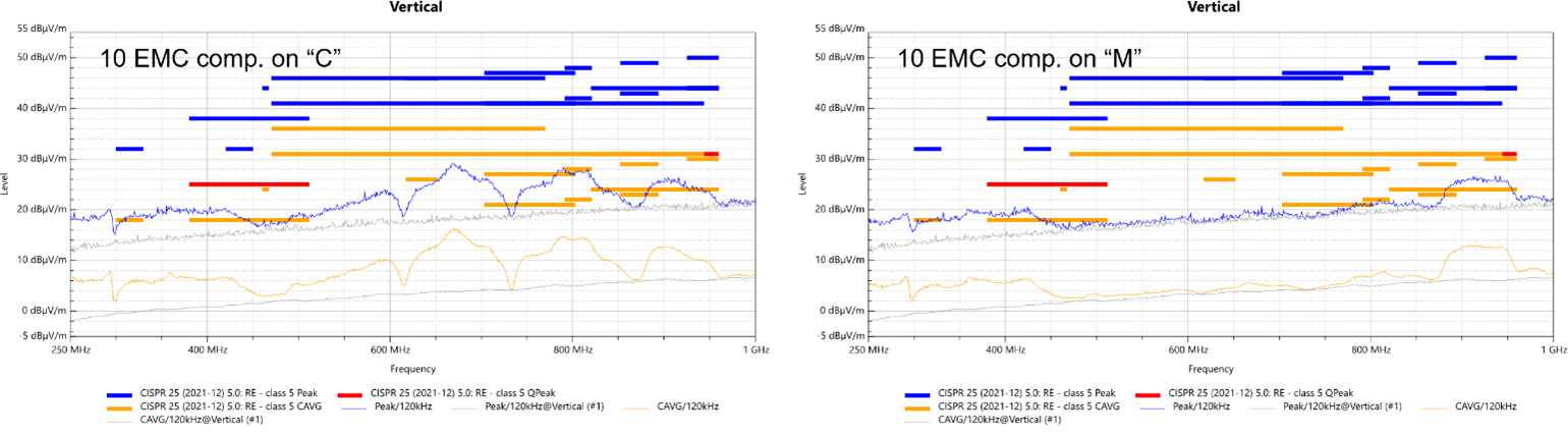
Figure 20: Vertical Log Periodic RE Measurement of the MPQ4323C-AEC1 (Left) and MPQ4323M-AEC1 (Right) for 10 EMC Components
Advanced EMC Performance of the MPQ4323M-AEC1
Figure 21 shows the switch-node waveform for the MPQ4323M-AEC1, which is close to an ideal square wave voltage.
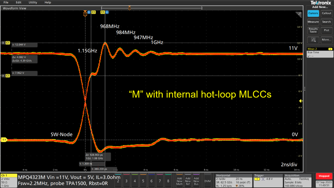
Figure 21: Switch-Node Waveform of the MPQ4323M-AEC1
The switch-node resonance frequency is about 1GHz with a low amplitude. The low amplitude indicates low RE. Due to the short ringing time, the antenna has low radiation capability.
Figure 22 shows the switch-node waveform of the MPQ4323C-AEC1.
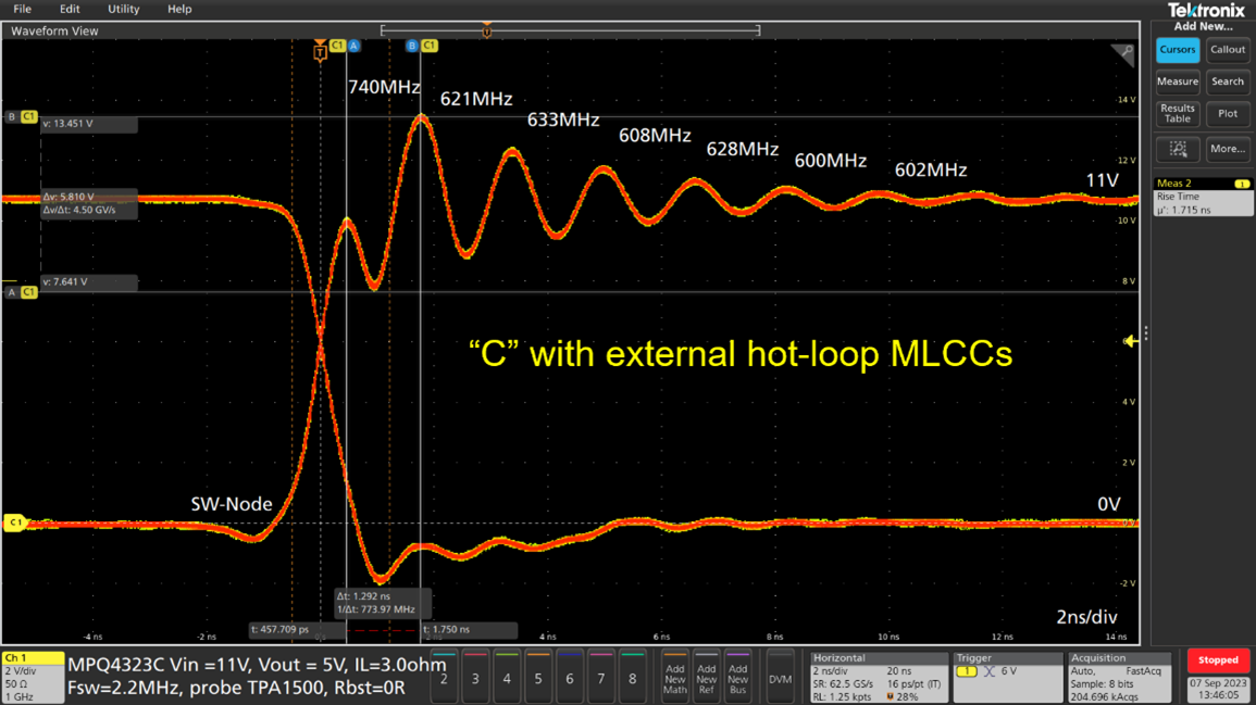
Figure 22: Switch-Node Waveform of the MPQ4323C-AEC1
The electrical connection between the hot-loop MLCCs and the MOSFETs is longer. This creates greater parasitic inductance that results in a higher amplitude resonance. The longer ringing time leads to increased radiation capability as an antenna.
VIN DC Voltage Waveform of the MPQ4323M-AEC1 "M" and Standard MPQ4323C-AEC1 "C"
Figure 23 shows the VIN waveform of the MPQ4323M-AEC1. The applied VIN DC voltage is almost free of a resonance amplitude, with no visible spikes. This is the main advantage of converter modules with internal hot-loop MLCCs.
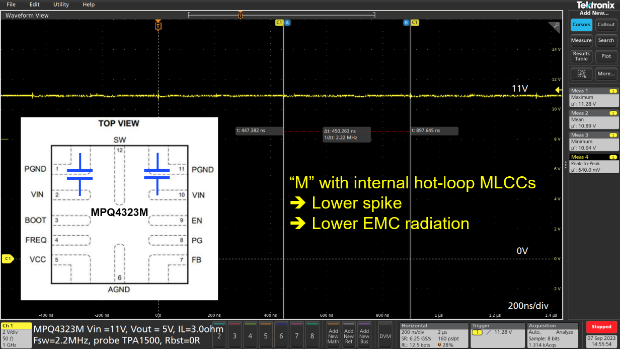
Figure 23: VIN DC Waveform (Pin 2 and Pin 10) of the MPQ4323M-AEC1
Figure 24 shows the VIN waveform of the MPQ4323C-AEC1. The VIN DC voltage is superimposed with the resonance that occurs in the switch node. The spike is a stimulus on the PCB traces, hot-loop MLCCs, and VIN pins that act as antennas radiating with the spike’s frequencies. The blue ESL traces are strong radiating traces on a step-down converter module. On a module, the blue ESL traces are less noisy compared to a standard step-down converter module.
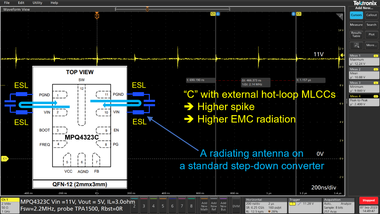
Figure 24: VIN DC Waveform (Pin 2 and Pin 10) on the MPQ4323C-AEC1
VIN AC Voltage Waveform of the MPQ4323M-AEC1 "M" and Standard MPQ4323C-AEC1 "C"
Figure 25 shows the AC VIN waveform for the MPQ4323M-AEC1 with a low spike resonance amplitude. The EMC filter does not need to attenuate a large resonance amplitude, which is an important advantage.
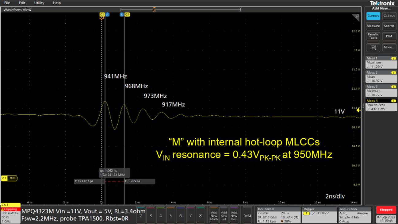
Figure 25: VIN AC Waveform (Pin 2 and Pin 10) on the MPQ4323M-AEC1
Figure 26 shows the AC VIN waveform for the MPQ4323C-AEC1 board with a large spike resonance amplitude. The EMC filter must attenuate the amplitude of this resonance to prevent RE from entering the PCB traces and the harness.
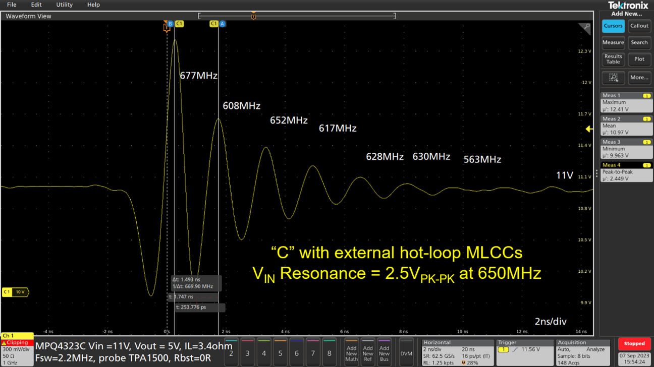
Figure 26: VIN AC Waveform (Pin 2 and Pin 10) on the MPQ4323C-AEC1
Conclusion
The common understanding that a module with two internal hot-loop MLCCs only reduces the component count by two capacitors is misplaced. The example in this application note demonstrated that the reduced number of capacitors is higher, with a minimum of four MLCCs that can be removed from the BOM. The MPQ4323M-AEC1 achieves excellent EMC performance compared to a traditional step-down converter.
The advantages of a converter module with very short, internal hot-loop connections directly on the lead frame are significant. The comparison of the DC waveforms in Figure 23 and Figure 24, and the comparison of the AC waveforms in Figure 25 and Figure 26 underline the advantage of short hot-loop connections. The RE comparison in Figure 20 further shows the advantage of internal hot-loop MLCCs.
This application note discussed the advantage of low EMC radiation using short, internal, hot-loop traces, which is difficult to compensate using many external EMC components.
Additional Reading
Contact an MPS FAE for additional support on EMC applications. MPS also has EMC laboratories in the USA, Germany, and China. Discover MPS’s broad range of automotive solutions.
_______________________
Did you find this interesting? Get valuable resources straight to your inbox - sent out once per month!
Technical Forum
 Latest activity a day ago
 2 Comments
Latest activity 2 days ago
2 Comments
Latest activity 2 weeks ago
3 Comments
2 Comments
Latest activity 2 days ago
2 Comments
Latest activity 2 weeks ago
3 Comments
Log in to your account
Create New Account