Optimizing Haptic HMIs for Reliability with Magnetic Sensors

Get valuable resources straight to your inbox - sent out once per month
We value your privacy
Introduction
Rotary dials are used in diverse applications for human-machine interfaces (HMI). Touch interfaces include the buttons, knobs, and dials on everyday devices, from automobiles and white goods, to the touch screen on your mobile phone. These devices not only translate human input into an electrical signal, but they also provide an important feature — haptic feedback. This is especially useful for safety-related functions in time-sensitive situations, such as when a user is inside a dark cockpit interior or adjusting the flow of a medical pump (see Figure 1). Buttons should be simple to locate by touch without the additional need for visual identification.
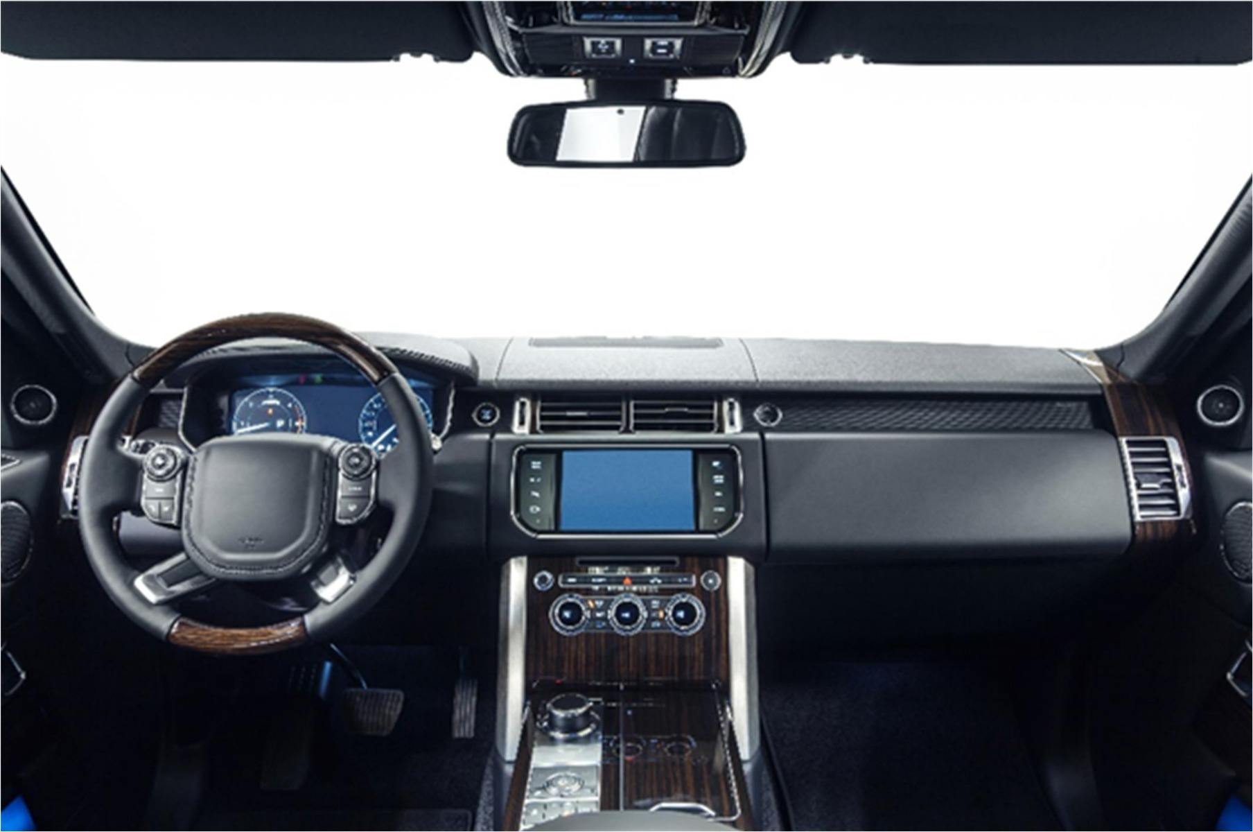
Figure 1: Interior Console and Steering Wheel Controls
However, new designs are constantly pushing the envelope to produce novel solutions that fit into new form factors, provide additional functions, and increase the lifetime of the HMI. Conventional buttons and rotary dials are often a limiting factor because they occupy significant volume, have a stiff coupling from the button down to the solder joints on a PCB, and their contacts are laid out for a specific, limited lifetime.
For example, many white goods have a simple, single-button interface on the faceplate. The complete machine (including the knob) is exposed to vibrations, temperature swings, and humidity across many hours of operation. This harsh environment adversely affects the lifetime of the knob, while the button’s shaft provides a path for humidity to get into other control electronics. Mitigating these issues can be expensive.
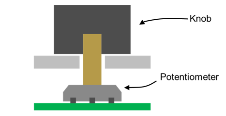
Figure 2: Conventional Rotary Dial Using a Potentiometer
Using modern magnetic sensors for HMI applications can significantly reduce the overall design cost, while simultaneously increasing reliability and mechanical design flexibility. This article provides insight into the fundamental ideas and design considerations that go into optimizing an HMI application.
Simple and Cost-Effective Sensing Principle
An integrated Hall-based magnetic angle sensor is fully equipped to detect the rotation of a magnetic field. For example, a sensor with a small indicator magnet attached to the rotating part produces a fully functional, contactless rotating knob. Simply place a magnetic angular sensor in-line with the rotation axis of the magnet to sense the actual rotary position of the knob through the magnet rotation. This sensor operates without requiring a mechanical connection between the electronics and the haptic rotor (e.g. a wiper potentiometer). Using a magnetic sensor creates a simple, highly reliable design with an extremely long life.
Figure 3 shows a rotary knob using the MA800, a magnetic sensor from MPS that was designed to improve HMI applications. The MA800 utilizes MPS’s proprietary SpinAxisTM technology, which allows angle sensors to be implemented in small, highly cost-effective packages.
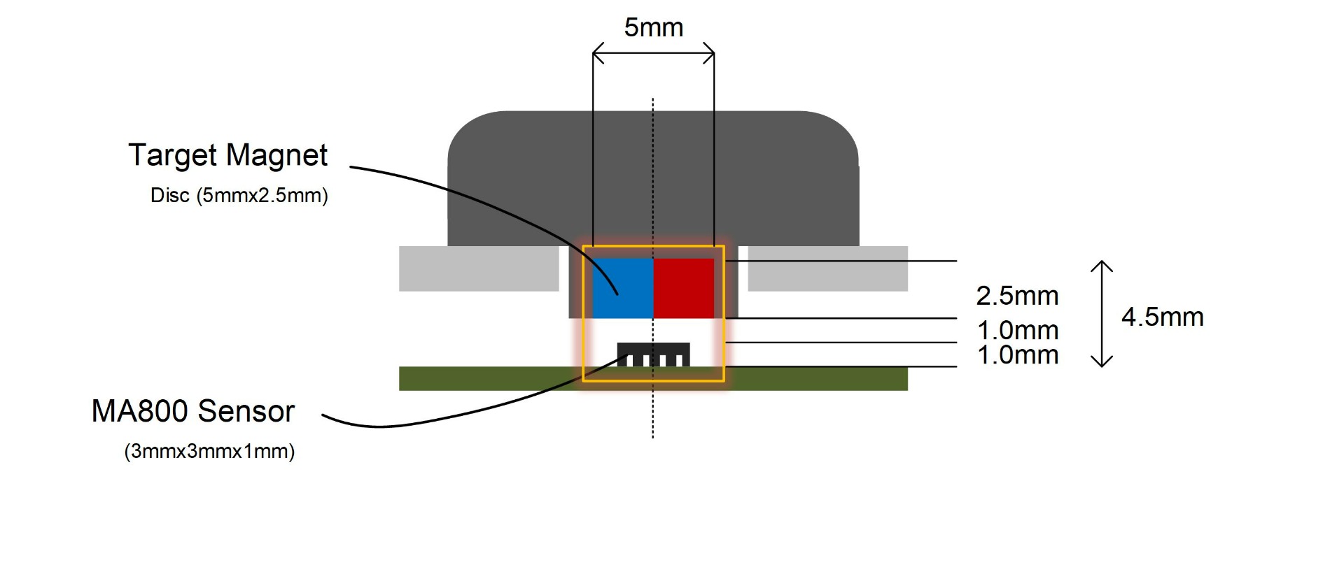
Figure 3: Cross-Section of a Rotary Knob with Magnetic Sensing
The whole magnet-sensor pair occupies a small volume, which leaves ample space to customize the haptic or optic appearance of the knob through bearings, detents, or light guides. The configuration shown in Figure 3 has a footprint of less than 5mmx5mm. This is a fraction of the size of a potentiometer alternative, which typically measures 10mm along a single edge.
Using a sensor from the MA8x0 family (the MA800, MA820, and MA850) allows the user to choose several methods to read the angle measurement. All sensors from this family feature a SPI interface, as well as an additional output (see Table 1).
Table 1: Additional Outputs for the MA8x0 Sensors
| Sensor | Additional Output |
| MA800 | SSI |
| MA820 | ABZ |
| MA850 | PWM |
Designing for Reliability and Meeting Manufacturing Tolerances
Magnetic sensors are highly reliable due to their contactless principle. This is in sharp contrast to their conventional counterparts — slip-ring potentiometers — which are notorious for their contact issues that result in a typical lifetime of about 250,000 cycles. However, magnetic sensors are also limited in certain ways. What are these limits and distortions, and how can they be avoided?
A first potential source of distortions are lateral displacements of the sensor versus the rotation axis (see Figure 4). These displacements can arise due to inaccuracies during production, or they may be created by the device’s wear and tear across its lifetime. This results in a magnetic nonlinearity that would be picked up by the sensor.
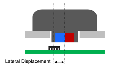
Figure 4: Sensor Lateral Displacement
For instance, using the set-up shown in Figure 3, a permitted magnetic mismatch of 0.5° or lower means that the lateral tolerance is limited to ±0.2mm — which is well within typical manufacturing tolerances. If for some reason more tolerance is required, then a larger magnet diameter or a ring magnet can be used to achieve a robust design. As an example, increasing the magnet diameter from 5mm to 8mm raises the lateral tolerance to ±0.4mm.
Figure 2 shows the relationship between the magnetic mismatch and different magnet diameters. Designers can use this relationship to choose a magnetic diameter than can accommodate for expected mechanical tolerances in their application.
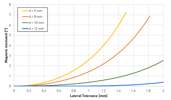
Figure 5: Maximum Mismatch vs. Lateral Tolerance for Different Magnet Diameters
The magnet’s dimensions are also vital to handling any variations for the airgap between the magnet and sensor. It is critical that such deviations do not drive the flux density at the sensor’s location outside of its required conditions. In Figure 3, the air gap could vary between 0.0mm and 3.1mm without exceeding the MA800’s specifications. Figure 6 shows this effect for several magnet diameters. This mechanical design flexibility can be used to meet manufacturing tolerance requirements by trading off air gap with the magnet size. For example, a wider target magnet enables a larger air gap.
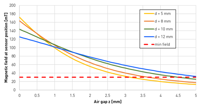
Figure 6: Intensity of the Magnetic Field vs. Air Gap for Different Magnet Diameters
Note that for this article, all magnetic analyses have been performed with a publicly available magnetic simulation tool. This simulator allows designers to run a quick check of specific magnetic configurations, and perform in-depth investigations on the impact of tolerances or misalignments.
Push-Button
Some HMI applications require a push-button in addition to rotary functionality. The MA800 detects a push-button event when changes in the airgap induce variations of the magnetic field strength. Figure 7 shows a typical structure for a push-button combination knob.
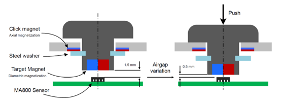
Figure 7: Cross-Section of a Rotary Knob with Push-Button Functionality
Figure 7: Cross-Section of a Rotary Knob with Push-Button Functionality Figure 8 shows the field gradient in relation to the magnet-to-sensor distance, as well as the difference between a single threshold and dual threshold (described below in detail). An axial displacement of 1mm, a nominal airgap of 1.5mm, and a pressed position with a 0.5mm gap produce a field difference of 60mT. The MA800 has adjustable magnetic thresholds to safely flag this transition through distinct output signals to a system controller.
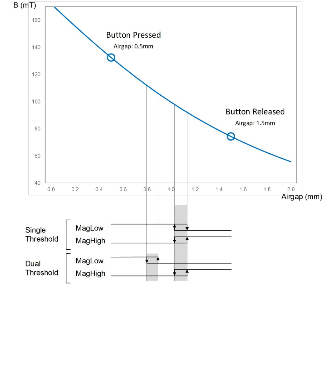
Figure 8: Push-Button Implementation with the MA800
This contactless process is a wear-free detection principle. It is important to ensure that no lifetime variations of the mechanism could deteriorate the sensing reliability. Figure 8 shows an overlay of the magnetic thresholds of the MA800, and their associated hysteresis intervals on top of the field strength curve for the typical configuration. The nominal magnetic set-up is designed in such a way that both endpoints have sufficient distance to the magnetic switching threshold, to ensure foreign particulates that may accumulate over time do not impede the mechanical travel to a point where the switching thresholds are not crossed.
When the magnetic field difference along the axial travel is large enough to securely pass more than one switching threshold, it is recommended to employ distinct thresholds to detect the high and low field strengths. Figure 8 shows a sketch for such a dual-threshold configuration. A dual threshold adds safety features to the overall application, as it detects mechanical faults in case the button gets stuck in a middle position.
When selecting a contactless sensing mechanism (and thereby removing contact issues from knobs and buttons), the push mechanism becomes the greatest limiting factor. Figure 7 also illustrates a concept in which an axially oriented click magnet attracts a steel ring on the shaft. The magnetic force between these two creates a threshold for the axial travel that can be easily tuned via material constants and coatings. In addition, this concept is free of wear over lifetime.
Selecting a Low-Power, Compact Solution
For low-power and battery-powered applications, MPS also offers the MA782. The same magnetic design principles as described for the MA800 also apply to the MA782. This sensor’s refresh rate is configurable and can reduce the average consumption of the sensor below 10µA.
In addition, the MA782 provides a dedicated signal that indicates when a movement has passed a certain angle threshold. In such a watchdog scenario, the angle sensor serves as wake-up trigger for the complete system and allows microcontrollers (MCUs) and displays to remain in sleep mode to save a significant amount of battery power.
As the MA782 also comes in a UTQFN-14 (2mmx2mm) package, it combines ultra-low power sensing with an ultra-small footprint. This unique combination is instrumental in emerging applications, such as wireless thermostats in homes or hinge controls in foldable mobile phones (see Figure 9).
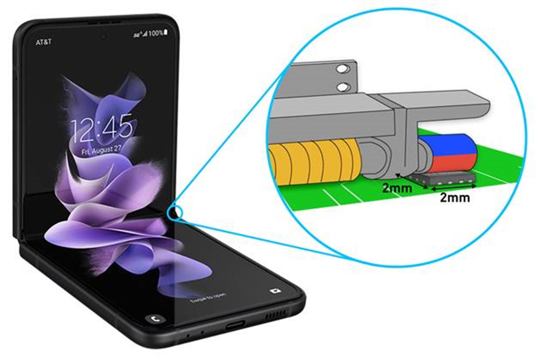
Figure 9: Foldable Phone Hinge with MA782 as Sensor and Watchdog
The small footprint and low-power functionality of these sensors make them well-suited for stringent designs where there is no room for a sensor (and PCB) to be placed on the axis of rotation, or at the end of the hinge. Devices like the MA782 sense the magnetic field away from the axis of rotation with special compensation to accurately recover the linear relationship between the mechanical angle and the sensor output.
Conclusion
When using magnetic sensors to implement HMI dials and buttons, there are various options to consider when designing the solution, such as decoupling the mechanics of the haptic elements and the electronics, as well as giving plenty of space to the surrounding mechanics. This article outlined simple design guidelines to engineer a contactless, cost-effective HMI solution with unparalleled longevity and low-power consumption.
_______________________
Did you find this interesting? Get valuable resources straight to your inbox - sent out once per month!
Technical Forum
 Latest activity 6 hours ago
 1 Comment
Latest activity a day ago
1 Comment
Latest activity 6 days ago
2 Comments
1 Comment
Latest activity a day ago
1 Comment
Latest activity 6 days ago
2 Comments
Log in to your account
Create New Account