Offline 140W PD3.1 Adapter
PFC + Flyback with the MPX2002

Get valuable resources straight to your inbox - sent out once per month
We value your privacy
1. Overview
1.1 Description
The EVX2002-44018A-00B is a 140W, USB Type-C power delivery (PD) 3.1 reference design board. It features a very small form factor with a high power density. Its electrical specifications are well-suited for cellphone and computer power adapters. The reference design board provides very low no-load power consumption, and its high overall efficiency meets DOE Level VI and CoC Tier 2.
The MP44018A is a critical conduction mode (CrM) / discontinuous conduction mode (DCM), multi-mode power factor correction (PFC) controller that provides simple and high-performance active PFC using minimal external components. The switching frequency (fSW) is reduced by dead time (DT) extension technology under light-load conditions, which improves light-load efficiency. The MP44018A also achieves reduced total harmonic distortion (THD) due to variable on-time control in DCM when compared to conventional constant-on-time (COT) control.
The MPX2002 is an all-in-one flyback controller with an integrated primary driving circuit, secondary controller, synchronous rectification driver, and safety-compliant feedback. The device offers the benefits of both primary-side regulation (PSR) and secondary-side regulation (SSR).The MPX2002 adopts novel quasi-resonant (QR) mode switching when it runs in DCM. Due to this feature, the power supply has improved efficiency. Under very light loads, the controller enters burst mode to achieve very low standby power consumption. The MPX2002 offers frequency jittering to help dissipate the energy generated by conducted noise.
The EVX2002-44018A-00B is a reference design for a universal offline, isolated power supply with a 28V/5A, 20V/5A, 15V/3A, 12V/3A, 9V/3A, or 5V/3A output. This datasheet contains the complete specification of the power supply, a detailed circuit diagram, the entire bill of materials required to build the power supply, a drawing of the transformers, and performance testing.
1.2. Features
- Wide Operating Input Voltage (VIN) Range (from 90V to 265V)
- High Power Density
- Low No-Load Consumption
- Meets DOE VI/CoC Tier 2 Efficiency
- Meets EN55022 Class B Emissions
- Surge Endurance: 2kV
- Short-Circuit Protection (SCP)
- Over-Voltage Protection (OVP)
- Under-Voltage Protection (UVP)
- Over-Temperature Protection (OTP)
1.3. Applications
- Laptop Charging
- Mobile Phone Charging
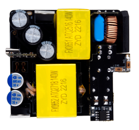
Figure 1: Top View
2 Reference Design
2.1 Block Diagram
Figure 2 shows the reference design board’s system block.
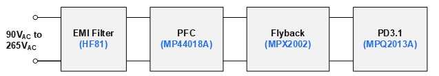
Figure 2: Block Diagram
2.2 Related Solutions
This reference design is based on the following MPS solutions:
Table 1: System Integrated Circuits
| MPS Integrated Circuit | Description |
| MPX2002 | All-in-one flyback controller |
| MP44018A | CrM/DCM multi-mode PFC controller |
| HF81 | X-capacitor bleeder |
| MPQ2013A | Low quiescent current linear regulator |
System Specifications
Table 2: System Specifications
| MPS Integrated Circuit | Description |
| Input voltage (VIN) range | 90VAC to 265VAC |
| Output voltage (VOUT) | 28/20/15/12/9/5V |
| Nominal load | 28V/5A, 20V/5A, 15V/3A, 12V/3A, 9V/3A, 5V/3A |
| PF | >0.93 at full load |
| Efficiency | >92.3% at full load |
| No Load-Consumption | <100mW |
| Output Voltage Ripple | <200mV |
| Line Regulation | <±3% |
| Load Regulation | <±3% |
| Short-Circuit Protection | Latch |
| Board form factor | 62mmx59mmx23.5mm |
3 Design
3.5 Schematics
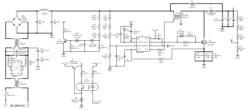
Figure 3: PFC Stage
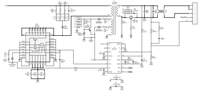
Figure 4: Flyback Stage
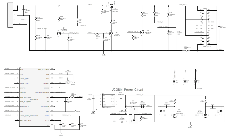
Figure 5: PD Output Stage
3.9 PCB Layout
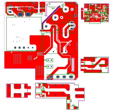
Figure 12: Top Layer
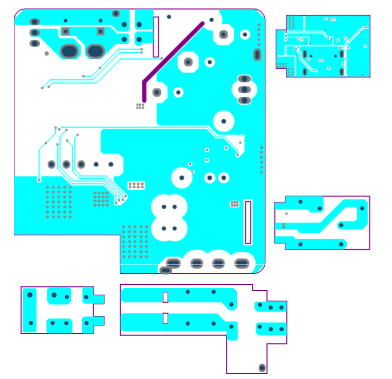
Figure 13: Mid-Layer 1
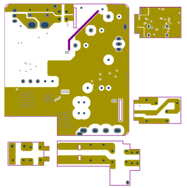
Figure 14: Mid-Layer 2
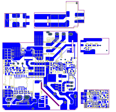
Figure 15: Bottom Layer
Log in to your account
Create New Account