MPQ7200 DRL-PL-TI Lamp Reference Design
Synchronous Buck-Boost Mode LED Driver for Automotive Systems

Get valuable resources straight to your inbox - sent out once per month
We value your privacy
1 Overview
1.1 Description
This reference design proposes a dual-channel buck-boost system for daytime running lamp (DRL), position lamp (PL), and turn indicator (TI) applications using the MPQ7200-AEC1. The MPQ7200-AEC1 is a high-frequency, constant-current LED driver with integrated power MOSFETs. The device offers a compact solution to achieve 1.2A of continuous output current (IOUT) across a wide input supply range, with excellent load and line regulation.
The EVQ7200-DRL-PL-TI-00A is a fully assembled and tested buck-boost mode LED driver reference design board. It has two buck-boost channels and generates an LED current up to 1A from a 6V to 20V input range.
1.2 Features
- Wide 6V to 42V Operating Input Range
- Buck-Boost Mode: Configurable 1.2A Continuous Output Current (IOUT)
- 44mΩ/40mΩ Internal Power MOSFETs
- Default 1.15MHz Switching Frequency (fSW) for Buck-Boost Mode with Spread Spectrum Meets CISPR25 Class 5
- PWM Dimming (100Hz to 2kHz Dimming Frequency)
- Internal, 500Hz Two-Step Dimming with Configurable Duty Cycle
- Fault Indication for LED Short (to GND and Battery), LED Open, Output Over-Voltage (OV) and Thermal Shutdown Conditions
- Over-Current Protection (OCP)
- Configurable Thermal Derating via NTC Remote Temperature Sensing
- EMI Reduction
- Available in a QFN-19 (3mmx4mm) Package with Wettable Flanks
- Available in AEC-Q100 Grade 1
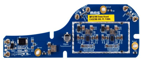
Figure 1: EVQ7200-DRL-PL-TI-00A
1.3 Applications
- Daytime Running Lights (DRLs)
- Position Lights (PLs)
- Turn Indicator Lights (TIs)
2 Reference Design
2.1 Block Diagram
The reference design offers a dual-channel buck-boost LED driver solution. It uses 2 LED drivers (MPQ7200-AEC1) to drive DRL-PL-TI lamps (see Figure 2).
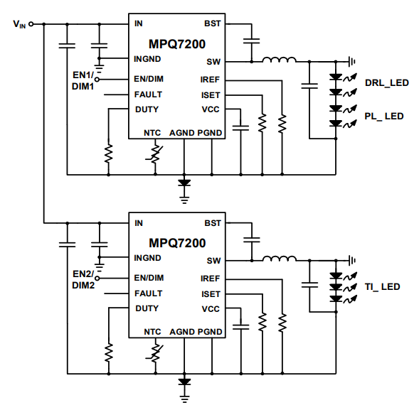
Figure 2: Buck-Boost Topology
2.2 Related Solutions
This reference design is based on the following MPS solutions:
Table 1: Related Solutions
| MPS Integrated Circuits | Description |
| MPQ7200-AEC1 | 42V, 1.2A buck-boost or 3A buck, synchronous LED driver, AEC-Q100 qualified |
2.3 System Specifications
Table 2: System Specifications
| Parameter | Specifications |
| Input voltage (VIN) range | 6VDC to 20VDC |
| Output LEDs | 4 LEDs and 3 LEDs |
| Output current (IOUT) | 1A |
3 Design
3.1 Schematic
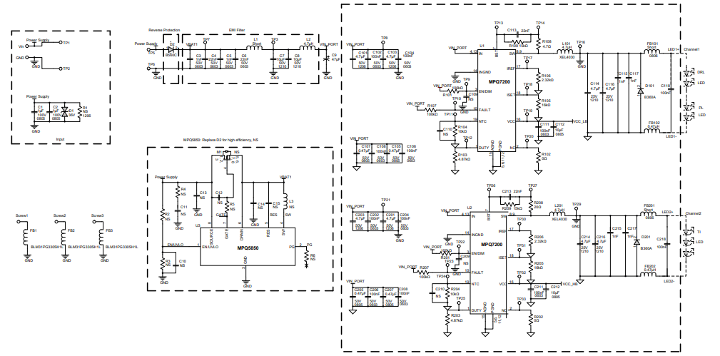
Figure 3: Reference Design Board Schematic
3.2 BOM
| Qty | Ref | Value | Description | Package | Manufacturer | Manufacturer PN |
| 2 | C1, C2 | 1µF | Ceramic capacitor, 100V, X7S | 0805 | TDK | C2012X7S2A105KT000N |
| 5 | C3, C5, C115, C117, C215, C217 | 1nF | Ceramic capacitor, 50V, X7R | 0603 | Murata | GRM188R71H102KA01D |
| 2 | C4, C6 | 22nF | Ceramic capacitor, 50V, X7R | 0603 | Murata | GCM188R71H223KA37D |
| 2 | C7, C8 | 10µF | Ceramic capacitor, 50V, X7R | 1210 | Murata | GRM32ER71H106KA12L |
| 1 | C9 | 47µF | Electrolytic capacitor, 50V | SMD | Panasonic | EEEFN1H470XP |
| 4 | C10, C11, C12, C13 | NS | Ceramic capacitor, 50V, X7R | 0603 | ||
| 1 | C14 | NS | Ceramic capacitor, 50V, X5R | 1206 | ||
| 1 | C15, C109, C110, C209, C210 | NS | Ceramic capacitor, 50V, X5R | 0805 | ||
| 4 | C101, C103, C201, C203 | 4.7µF | Ceramic capacitor, 50V, X7R | 1206 | Murata | GRM31CR71H475KA12L |
| 2 | C113,C213 | 22nF | Ceramic capacitor, 50V, X7R | 0402 | Murata | GCM155R71H223JA |
| 10 | C102, C104, C106, C108, C111,C202, C204, C206, C208, C211 | 100nF | Ceramic capacitor, 50V, X7R | 0603 | Murata | GCJ188R71H104KA12D |
| 4 | C105, C107, C205, C207 | 470nF | Ceramic capacitor, 100V, X7R | 0805 | Murata | GRM21BR72A474KA73L |
| 2 | C112, C212 | 10µF | Ceramic capacitor, 16V, X7S | 0805 | Murata | GRM21BC71C106KE11L |
| 2 | C114, C116, C214, C216 | 4.7µF | Ceramic capacitor, 25V, X7R | 1210 | TDK | C3225X7R1E475M |
| 1 | C118, C218 | 100nF | Ceramic capacitor, 25V, X7R | 0603 | Murata | GCJ188R71E104KA12D |
| 1 | D1 | 36V | TVS, 36V | DO-214AC | Bournes | SMAJ36CA-Q |
| 1 | D2 | 60V | Diode, 60V, 5A | SMC | Diodes | B560C-13-F |
| 2 | D101, D201 | 60V | Diode, 60V, 3A | SMA | Diodes | B360A-13-F |
| 3 | FB1, FB2, FB3 | 6A | Magnetic bead, 6A | 1206 | Murata | BLM31PG330SH1L |
| 2 | FB101, FB201 | Short | Film resistor, 1% | 0805 | Yageo | RC0805FR-070RL |
| 1 | L1 | Short | Film resistor, 1% | 0805 | Yageo | RC0805FR-070RL |
| 1 | L2 | 4.7µH | Inductor, 4.7ΩH, 36mΩ, 5.9A | SMD | Coilcraft | XAL5030-472MEB |
| 1 | L3 | NS | Inductor | SMD | ||
| 1 | L101, L201 | 4.7µH | Inductor, 4.7µH, 44.1mΩ, 5.1A | SMD | Coilcraft | XEL4030-472MEB |
| 1 | M1 | NS | N-channel MOSFET | SO-8 | ||
| 1 | R1 | NS | Film resistor | 1206 | ||
| 1 | R2 | NS | Film resistor, 5% | 0603 | ||
| 3 | R3, R4, R6 | NS | Film resistor, 5% | 0603 | ||
| 1 | R5 | NS | Film resistor, 5% | 0603 | ||
| 3 | R101, R201 | 100kΩ | Film resistor, 1% | 0603 | Yageo | RC0603FR-07100KL |
| 2 | R102, R202 | 0Ω | Film resistor, 1% | 0603 | Yageo | RC0603FR-070RL |
| 2 | R103, R203 | 4.87kΩ | Film resistor, 1% | 0603 | Yageo | RC0603FR-074K87L |
| 2 | R102, R204 | 10kΩ | Film resistor, 1% | 0603 | Murata | RC0603FR-0710KL |
| 2 | R105, R205 | 16kΩ | Film resistor, 1% | 0603 | Yageo | RC0603FR-0716KL |
| 2 | R106, R206 | 2.32kΩ | Film resistor, 1% | 0603 | Yageo | RC0603FR-072K32L |
| 1 | R107, R207 | 100kΩ | Film resistor, 1% | 0402 | Yageo | RC0402FR-07100KL |
| 2 | R108, R208 | 20Ω | Film resistor, 1% | 0402 | Yageo | RC0402FR-0720RL |
| 2 | R109, R209 | 15kΩ | Film resistor, 1% | 0402 | Yageo | RC0402FR-0715KL |
| 2 | GND, Vin, LED1+, LED1-, LED2+, LED2- | 2mm | Golden pin | DIP | Custom | Any |
| 2 | FB102, FB202 | MPL-AT2010-R47 | Inductor, 470nH, 27mΩ, 4.4A | SMD | MPS | MPL-AT2010-R47 |
| 2 | U1, U2 | MPQ7200-AEC1 | Synchronous LED driver | QFN-19 (3mmx4mm) | MPS | MPQ7200GLE-AEC1 |
| 1 | U3 | MPQ5850 (optional) | Smart diode controller, 36V | TSOT23-8 (2mmx3mm) | MPS | MPQ5850GJ-AEC1 |
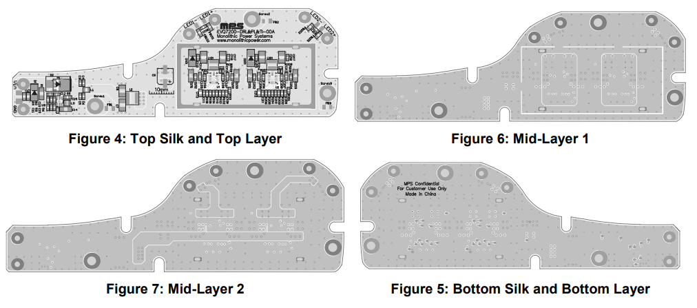
3.3 PCB Layout
4 Test Results
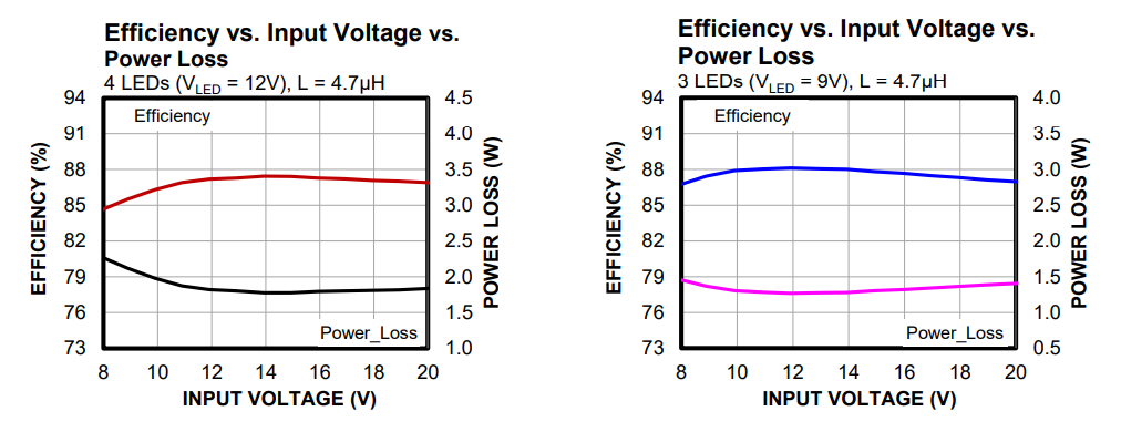
4.1 Efficiency
Buck-boost mode, L = 4.7µH, ILED = 1A, fSW = 1.15MHz, channel 1: 4 LEDs (VLED1 = 12V), channel 2: 3 LEDs (VLED2 = 9V), TA = 25°C, unless otherwise noted.
Log in to your account
Create New Account