AN185 - MPQ5850: 36V, Smart Diode Controller with Reverse Protection, AEC-Q100

Get valuable resources straight to your inbox - sent out once per month
We value your privacy
Abstract
The MPQ5850 is a 36V, smart diode controller with reverse polarity protection designed for automotive applications.
The device can rectify alternating voltages up to 100kHz. For example, the MPQ5850 can rectify alternating voltages for a faulty automotive alternator or DC switching power supply.
In switching applications (e.g. O-rings), the MPQ5850 prevents negative currents from flowing back through a power supply unit or a battery.
The MPQ5850 can replace a power diode or an unregulated P-channel MOSFET rectifier solution with a regulated N-channel MOSFET. Replacing either of these with the MPQ5850 reduces power loss and temperature.
Introduction
The MPQ5850 drives an external N-channel MOSFET and converts it to an active diode with a 20mV forward voltage drop. AN185 shows examples of this, such as LV124 AC rectification, ISO pulses, and parallel connection of voltage sources (e.g. O-rings).
MPQ5850 Applications
The MPQ5850 applications are listed below:
- Automotive System Protections, Reverse Polarity
- Automotive Systems, LV124 and ISO Pulses
- Automotive Advanced Driver-Assistance Systems (ADAS), Cameras
- Automotive Infotainment Systems, Including Digital Clusters and Head Units
- Battery-Powered Systems
- O-Rings
EVQ5850-J-00A Evaluation Board
The EVQ5850-J-00A is an evaluation board designed to demonstrate the capabilities of the MPQ5850. A large number of circuits can be tested on the evaluation board. The EVB layout also allows EMC filters to be tested at the input and the output.
Evaluation Board Layout
Figure 1 shows the evaluation board with a TVS diode, an optional EMC input filter, and an optional EMC output filter, prepared for different MOSFET packages.
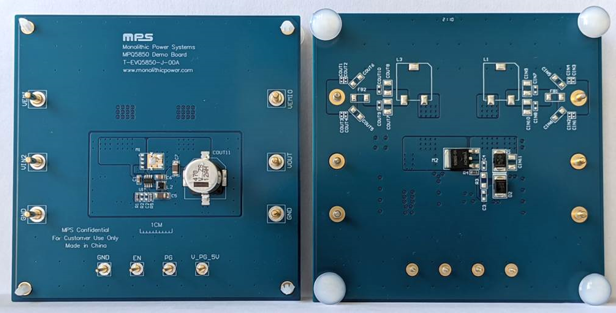
Figure 1: EVQ5850-J-00A (4-Layer PCB)
Basic Automotive Measurements
Figure 2 shows the typical application circuit used for LV124 and ISO pulse measurements. This circuit is suitable for a wide range of applications.
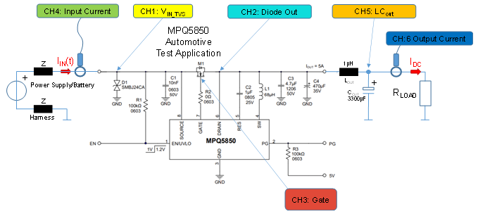
Figure 2: MPQ5850 Automotive Test Application for LV124 and ISO Pulse Measurements (1) (2)
Notes:
1) C1, C3, D1, and LCOUT can be different from the values listed in Figure 2. The minimum C1 is 10nF. A larger C1 improves the stability of the source voltage (VSOURCE). Choose C1 to meet the application’s EMC requirements.
2) The C3 capacitor is optional. C3 rejects EMC transients between VSOURCE and the drain voltage (VDRAIN). The MPQ5850 is supplied by VDRAIN internally. C3 can be below 4.7µF.
LV124 Measurement
LV124 is a quality and reliability test standard jointly established by German automotive manufacturers, applied to in-vehicle electric components for the 12V electrical system.
The LV124 measurements are made using an Ametek 200Q series voltage-drop simulator (VDS 200Q) and a 180cm harness with an impedance (Z). Each power supply line consists of an impedance (Z) that is measured with an impedance LCR meter for inductance (L) and resistance (R). The impedance (Z) can be calculated with Equation (1):
$$Z = L(µH) + R(mΩ)$$Where L is 1.1µH, R is 17.5mΩ, and the harness length is 180cm.
ISO 7637-2 Pulse Measurement
The ISO 7637-2 standard defines specific test methods and procedures to ensure that a part’s conducted electrical transients are compatible with the passenger cars and commercial vehicles (with 12V or 24V electrical systems) in which the part is installed.
The pulse measurements are made using an Ametek 200N series ultra-compact simulator (UCS 200N), a 200N series load dump generator (LD200N), a 50cm harness with an impedance (Z), and thin lab cables. The impedance (Z) can be calculated with Equation (1). Where L is 0.5µH, R is 15mΩ, and the harness length is 50cm.
Select the optional LCOUT filter for the desired hold-up time. Select D1 for the required pulse strength.
Optional LCOUT Not In Use
The C4 capacitor should be ≥220µF; however, it is recommended that C4 be ≥470µF.
Control Modes
The MPQ5850 has two control modes: mode A and mode B. The MOSFET source to drain voltage (VSOURCE_DRAIN) can be calculated with equation (2):
$$V_{SOURCE\_DRAIN} = I_{DRAIN} \times R_{(DS)ON}$$Where IDRAIN is the drain current, and R(DS)ON is the on resistance.
In mode A, VSOURCE_DRAIN is in regulation (20mV), and the MOSFET operates within the analog range. R(DS)ON is set at a higher value than the minimum R(DS)ON. The MPQ5850 control loop adjusts R(DS)ON for a constant 20mV VSOURCE_DRAIN.
In mode B, VSOURCE_DRAIN is not in regulation (>20mV), and the gate to source voltage (VGATE_SOURCE) turns on the MOSFET fully. R(DS)ON is set to the minimum R(DS)ON value. The MPQ5850 drives VGATE_SOURCE to its maximum voltage (12V).
The MPQ5850 transitions between mode A and mode B automatically.
If the rated current is low, then the MPQ5850 operates in mode A. If the rated current is high, then the device operates in mode B.
Select the MOSFET according to the desired RDS(ON) and power dissipation. The MPQ5850 can drive most common-sized N-channel MOSFETs. This included both standard and logic-level MOSFETs.
Mode A (VSOURCE_DRAIN Is in Regulation)
Figure 3 shows a measurement in mode A. VGATE_SOURCE is 9.935V, which is below the maximum VGATE_SOURCE (12V). The MOSFET has not reached the minimum RDS(ON). VSOURCE_DRAIN is measured using a digital multimeter.
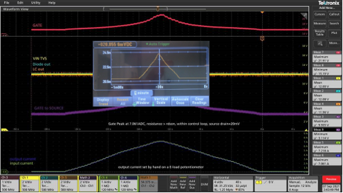
Figure 3: Mode A (VSOURCE_DRAIN = 20mV, ILOAD = 7A)
Mode B(VSOUCE_DRAIN Is Not in Regulation)
Figure 4 shows a measurement in mode B. VGATE_SOURCE is 12.21V, which exceeds the maximum VGATE_SOURCE (12V). The MOSFET has reached the minimum RDS(ON). VSOURCE_DRAIN is measured using a digital multimeter.
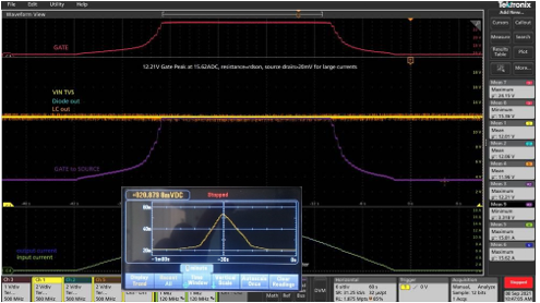
Figure 4: Mode B (VSOURCE_DRAIN = 54mV, ILOAD = 12A)
_______________________
Did you find this interesting? Get valuable resources straight to your inbox - sent out once per month!
Technical Forum
 Latest activity a week ago
 3 Comments
Latest activity 2 weeks ago
2 Comments
Latest activity 4 weeks ago
4 Comments
3 Comments
Latest activity 2 weeks ago
2 Comments
Latest activity 4 weeks ago
4 Comments
Log in to your account
Create New Account