Using Thermal Derating to Extend Automotive LED Life Expectancy: A Simple and Cost-Effective Solution
DOWNLOAD PDF

Get valuable resources straight to your inbox - sent out once per month
We value your privacy
Abstract
Automotive manufacturers are adopting more and more LED lightning technology due to its low power consumption and extended lifecycle. However, when the latest technology trends are paired with challenging automotive requirements, there is an increased demand to design solutions that can avoid thermal breakdown while lengthening the life expectancy of the LEDs. This article will present a simple, low-cost, NTC-based circuit with linear dimming that can drive current according to the temperature, which results in a more effective automotive LED lighting solution.
First, we will briefly review the problem and the motivation for the automotive lighting solution design. Second, the sensing circuit is presented together with the simulation results. Finally, the simulation results are verified with real tests, the results of which are covered in the last section.
Background
LED lighting is a technological innovation that comes with additional design challenges. To avoid thermal breakdown, LED lighting systems must be designed while considering the components’ thermal characteristics. This is especially important in applications such as automotive lighting, where high ambient temperatures and long operating times can cause components to deteriorate rapidly.
The evolution of automotive lighting technology — which has resulted in increased drive currents and demands for ever-smaller package sizes — has made optimizing a thermal design both more difficult and more necessary. Higher drive currents increase junction temperatures to the point that optimized heat dissipation is insufficient. Therefore, a method must be created to reduce the LED current when the temperature is too high.
Most automotive LED drivers include current dimming capability. For example, MPS’s MPQ2489 implements both PWM and analog dimming using the DIM pin. However, dimming control circuits are typically controlled through a potentially complex analog or digital circuit, which usually takes up a significant amount of space in the final application and increases the overall system cost. This article presents a simple NTC-based circuit solution to linearly dim the output current according to the temperature
Figure 1 shows a circuit that is designed to maintain a stable nominal output current in the driver when the temperature is below 70°C. If the circuit exceeds the temperature threshold, the output current decreases in a quasi-linear relation to the temperature in order to avoid thermal breakdown, reaching a minimum current value when the LEDs reach the maximum rated temperature (about 120°C).
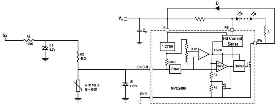
Figure 1: MPQ2489 Circuit Schematic
Sensing Circuit
As an example, the circuit presented in this article references the MPQ2489-AEC1, a 60V, 1A, automotive-grade buck LED driver from Monolithic Power Systems. This driver implements both PWM and analog dimming, though only the latter is used in this application. To use the analog dimming capability, a DC voltage between 0.3V and 2.5V must be applied to the DIM pin. This voltage can linearly regulate the LED current between 250mA and 1.1A (see Figure 2). When the DC voltage ranges between 0.3 and 1.25V, it yields a current between 250mA and 550mA.
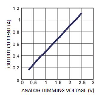
Figure 2: MPQ2489-AEC1 Analog Dimming Curve
The temperature is sensed using an NTC thermistor (NTCG164BH103JTDS from TDK), which is implemented in a voltage resistor divider. The varying NTC resistance causes the voltage at the divider’s output to change according to the temperature. This shifts the voltage on the DIM pin, which consequently alters the output current.
The nominal voltage applied to the DIM pin is set by a 1.25V voltage reference. This ensures a stable input voltage for temperatures below the 70°C threshold. Furthermore, the resistor divider’s supply voltage is fixed at 6.2V using a 250mW Zener diode.
While the device is 70°C or cooler, the 1.25V supplied by the voltage reference limits the DIM input, and a current of 550mA is supplied to the LEDs. Once the temperature surpasses the 70°C threshold, the resistor divider output drops below 1.25V. Then the DIM input follows the resistor divider profile, which reduces the LED drive current as the temperature continues to rise.
Simulations can be used to estimate the circuit’s operation. The results of the simulation for this example show that the DIM voltage is stable at 1.25V up to the temperature threshold, and then decreases exponentially until it reaches the 0.3V minimum output when the temperature reaches 120°C (see Figure 3).
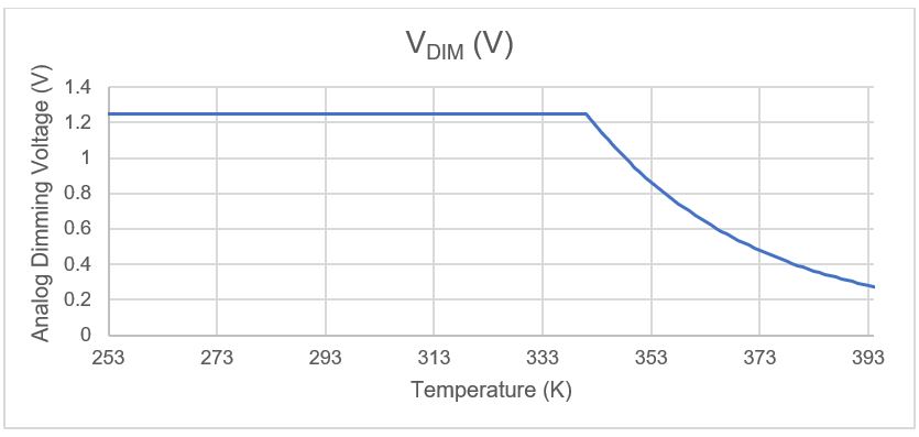
Figure 3: Simulation Result
One drawback of this system is how the NTC resistance varies according to temperature following the Steinhart-Hart equation, calculated with Equation (1):
$$R=R_0 \times e^{B\times({1\over T} - {1 \over T_0})}$$The Steinhart-Hart equation indicates that the relationship between the temperature and the resistance value of the NTC is nonlinear, so the resistor divider also has a nonlinear relationship with temperature. Consequently, the decrease in current due to temperature is also nonlinear. This decrease can be estimated with Equation (2):
$$V_{DIM} = V_{IN} \times \frac {R_{NTC}}{R_2+R_{NTC}} = V_{IN} \times \frac {e^{B \times (\frac {1}{T} - \frac {1}{T_0})}}{ {R_2 \over R_0} + e^{B \times (\frac {1}{T} - \frac {1}{T_0})}}$$Despite that, the circuit offers a small and simple solution to diminish the LED driving current at high temperatures, which increases the life expectancy of these components.
Verification of Results
To test the circuit performance, a system was built to emulate a real-world use case (see Figure 4). The LEDs were substituted for a 3Ω resistor that is heated by applying a voltage difference across its poles. Then, the selected NTC was attached to the resistor with thermal paste to ensure maximally accurate resistor/temperature sensing. Finally, the NTC was connected to the designed circuit. By changing the temperature of the resistor (sweeping the power supplied to it), a DIM voltage curve was obtained.
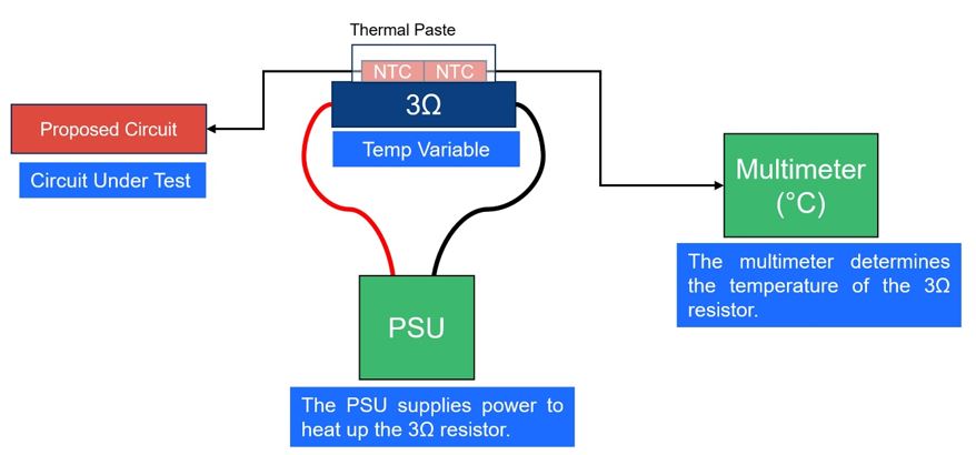
Figure 4: Test Set-Up
The test was carried out across a temperature range of 25°C to 145°C. Figure 5 shows that the expected circuit performance was achieved. While the temperature was below 74°C (which is close to the estimated 70°C threshold), the circuit’s output voltage (VDIM) remained stable at 1.25V. Beyond this temperature, the voltage dropped down to 0.25V at 145°C.
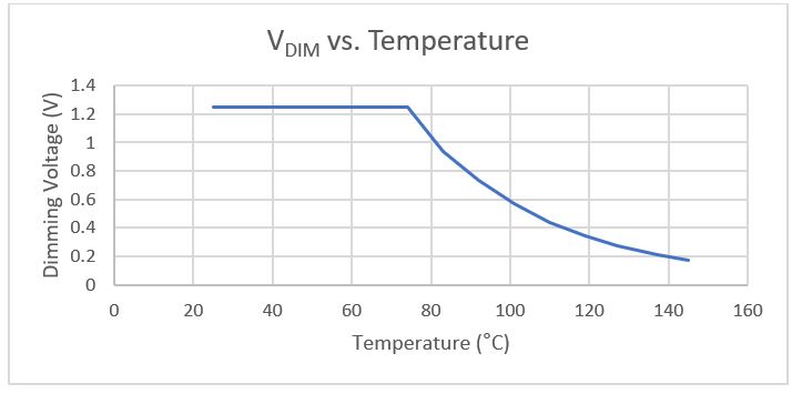
Figure 5: Test Results: Dimming Voltage as a Function of Temperature
Figure 6 shows that the obtained drive current is set to 100% when the LED temperature is below 74°C. Once the temperature exceeds this value, the drive current is dimmed to reduce the heat dissipation and counteract the rising temperature. This test, as well as the test done for Figure 5, confirm the expected functionality of the design. By successfully limiting the output current at high temperatures, the circuit’s components are protected from thermal damage.
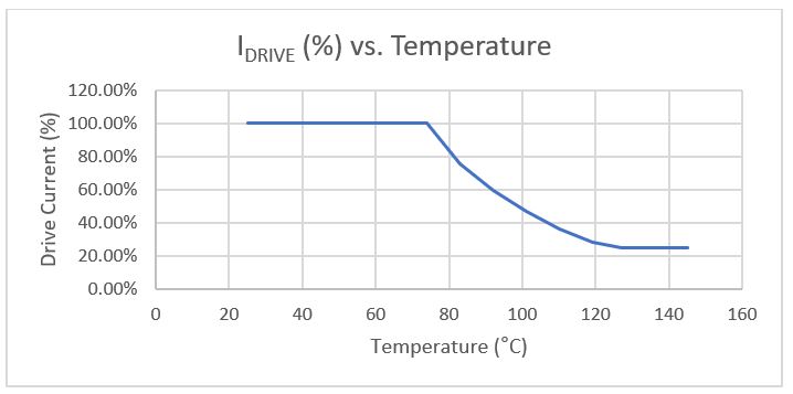
Figure 6: Test Results: Drive Current as a Function of Temperature
Summary
This article successfully demonstrated the implementation of a circuit that can control the drive current of LEDs by using a simple sensing circuit and preexisting dimming capabilities present in most LED drivers, such as the MPQ2489-AEC1 from MPS.
This solution offers automotive lighting system manufacturers a stable, cost-effective option that can significantly add to the life expectancy of the components in the circuit while taking up very little board space. The circuit proposed in this article can be applied to many existing lighting systems with relative ease and an inexpensive bill of materials, while demonstrating the reliability and flexibility of driver ICs.
_______________________
Did you find this interesting? Get valuable resources straight to your inbox - sent out once per month!
Technical Forum
 Latest activity a day ago
 2 Comments
Latest activity 2 days ago
2 Comments
Latest activity 2 weeks ago
3 Comments
2 Comments
Latest activity 2 days ago
2 Comments
Latest activity 2 weeks ago
3 Comments
Log in to your account
Create New Account