The Power Over Ethernet (PoE) Powered MP8030

Get valuable resources straight to your inbox - sent out once per month
We value your privacy
Introduction
With the abundance of electronic products, it is easy for desktops to become cluttered between various desktop power and signal interface cables. The development of Power over Ethernet (PoE) has resolved the challenge of managing multiple wires.
What is PoE?
PoE provides DC power while transmitting data signals for IP-based terminal equipment without changing the existing Ethernet Category 5 cabling infrastructure (see Figure 1).
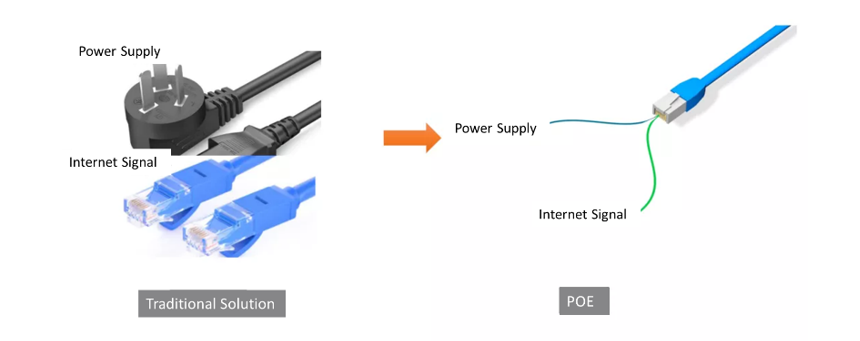
Figure 1: Traditional Solution vs. PoE
Common IP terminals include telephones, routers, and security cameras. Current 5G small base stations and many IoT terminals require PoE power supply. In addition, some applications also transmit audio signals through PoE, such as PoE audio.
Development of the PoE Standard
Figure 2 shows the evolution of PoE from 2003 through 2018.
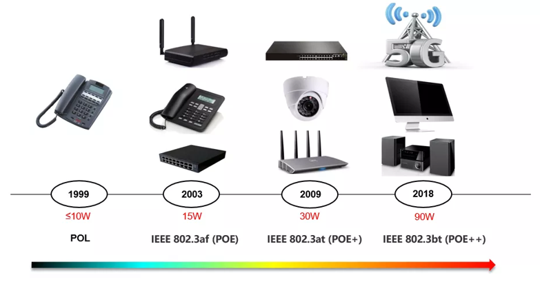
Figure 2: Evolution of PoE
PoE defined power delivery by establishing the first-generation IEEE 802.3af standard in 2003. Over time, PoE power has increased from 15W to 90W, supporting the expansion of terminal equipment from telephones to higher power TVs, IoT devices, and even 5G base stations.
PoE Trends with the MP8030
The MP8030 is a flyback/forward controller for the new generation of PoE-powered devices (PD). It is compliant with IEEE 802.3af/at/bt specifications.
Figure 3 shows the typical application of the MP8030.
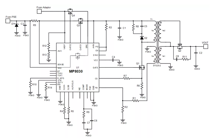
Figure 3: MP8030 Typical Application Circuit
The features of the MP8030 include:
- Powered Device (PD):
- Compliant with 802.3af/at/bt specifications
- Internal hot-swap MOSFET for ≤51W designs
- External FET with GATE1 for >51W designs
- GATE2 N-channel MOSFET driver for adapter supply
- Automatic maintain power signature
- Supports automatic classification
- DC/DC Design:
- Supports flexible DC/DC topologies:
- Primary-side regulation (PSR) flyback
- Secondary-side regulation (SSR) flyback
- SSR active-clamp forward
- Current source capability: 2A GATE driver, 0.8A SYNC driver
- 15ms soft-start time (tSS)
- EMI-optimized for conducted emissions (CE) and radiated emissions (RE) testing
The MP8030 has many advantages for design, performance, and safety requirements, which we will explore in further detail below.
Simplified Design
By integrating the bt power level of a PD and a DC/DC converter in a small QFN-32 (5mmx6mm) package, the MP8030 reduces PCB layout and eliminates the need to select PoE PDs. In addition, the terminal isolation step-down circuit works. These factors can mitigate complicated post-processing considerations.
MPS also provides custom reference designs for peripheral circuits and power supplies according to the system requirements.
High-Efficiency Performance
Figure 4 shows the efficiency curve of the MP8030 under the following test conditions: VIN = 54V, VOUT = 12V, and IOUT = 6A.

Figure 4: MP8030 Efficiency Curve
The MP8030 can reach a maximum efficiency of 93.8%. The market solution is typically a diode. However, the diode’s voltage drop reduces system efficiency. The MP8030’s built-in N-channel MOSFET Driver (GATE2) drives low on resistance (RDS(ON)) N-channel MOSFET (Q4) to replace the diode, effectively addressing the challenge to system efficiency.
Flexible Isolation Design Options
There are three topologies that the MP8030 can support simultaneously: PSR flyback, SSR flyback, and SSR active-clamp forward. These topologies can be divided between two modes of voltage control: PSR mode and SSR mode.
PSR Mode
Compared to traditional flyback topologies with optocoupler feedback, the MP8030 in PSR mode can detect the auxiliary winding voltage from the FB pin during the secondary-side output diode conduction period. This mode supports flyback topology.
SSR Mode
Meanwhile the COMP pin detects the VOUT feedback signal in SSR mode. The MP8030 maintains fixed frequency while the COMP voltage regulated peak current until triggering power saving mode (PSM). This mode supports both flyback and forward topologies.
Excellent Thermal Performance
Figure 5 shows the MP8030's thermal perfomance.

Figure 5: MP8030 Thermal Performance
At 72W of output power, the transformer has the highest heat generation. The transformer’s final temperature rise is 41°C, from 25.8°C to 67.4°C.
EMI Compliance
Figure 6 shows how the MP8030 successfully passed both conducted emissions (CE) and radiated emissions (RE) tests for EMI.
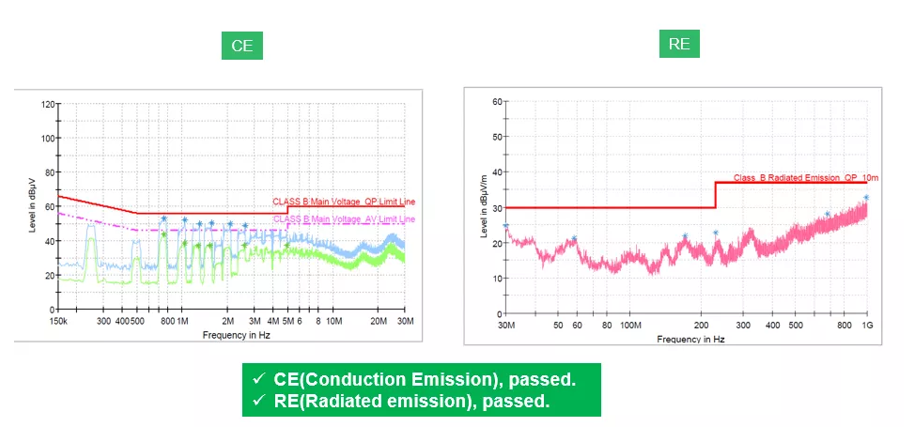
Figure 6: MP8030 CE and RE Results
Among the available bt solutions, the MP8030 can support up to 71W and offers features that significantly outpace comparable products in the market. Table 1 shows a comparison between the MP8030 and other bt solutions in the market.
Table 1: MP8030 vs. Other bt Solutions
| Parameter | MP8030 | Other bt Solutions |
| Integration | PD + DC/DC | PD + DC/DC |
| Maximum power | 71W (Class 8) | 51W (Class 6) |
| Detection | Built-in | External |
| Hot-swap MOSFET | 0.35Ω built-in MOSFET for 51W | 0.3Ω built-in MOSFET for 51W |
| External MOSFET for 71W | N/A | |
| Built-in MOSFET driver for adapter auxiliary power supply | Yes | No |
| Automatic maintain power signature characteristics | Yes | Yes |
| Automatic power identification (AutoClass) | Yes | No |
| Gate drive sink/source capability | 1.7A/2A | 0.85A/0.5A |
| Current sampling | 0.16V (low power loss) | 0.25V (high power loss) |
| EMI optimization | Frequency jittering | Frequency jittering |
| Package | QFN-32 (5mmx6mm) | VSON-45 (5mmx7mm) |
Conclusion
This article covered the evolution of the PoE standard and the features offered by the MP8030, such as IEEE 802.3af/at/bt functionality. The MP8030 is an excellent bt solution with benefits including simplified design, high efficiency, flexible isolation design options, excellent thermal performance, and EMI compliance.
_______________________
Did you find this interesting? Get valuable resources straight to your inbox - sent out once per month!
Technical Forum
 Latest activity 10 hours ago
 1 Comment
Latest activity 2 days ago
1 Comment
Latest activity 3 days ago
4 Comments
1 Comment
Latest activity 2 days ago
1 Comment
Latest activity 3 days ago
4 Comments
Log in to your account
Create New Account