Power Supply Design for Car Infotainment Systems (Part I)

Get valuable resources straight to your inbox - sent out once per month
We value your privacy
Introduction
A car’s infotainment system is an on-board, integrated information processing system based on the car’s bus body and internet. Vehicles have become more integrated and modular as consumers continue to raise expectations for driving, car information resources, entertainment, and safety. This trend has introduced new challenges to the research and development of car infotainment systems, particularly in power supply design stage.
This article is the first part of a two-part series covering power supply design for car infotainment systems. Part I will discuss the characteristics of primary and secondary power supplies. Part II will introduce solutions for surround-view camera power supplies, as well as a general car USB connection port.
Figure 1 shows the typical power architecture for car machine systems. Generally, a primary low-dropout (LDO) powers the microcontroller unit (MCU) and controller area network (CAN) modules for system monitoring and start-up. Two DC/DC converters power the main processor core board and other peripheral modules, such as the serializer, deserializer, and tuner IC. A separate power supply powers the camera module. Lastly, there is a dedicated USB charger IC for the USB port on the car’s front panel.
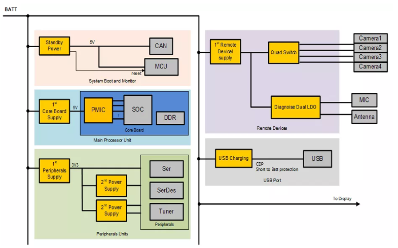
Figure 1: Typical Power Architecture of Car Machine Systems
The sections below examine the key performance metrics to select primary and secondary power supplies.
Characteristics of a Primary Power Supply
The system’s primary power supply is directly connected to the on-board battery. This system must be able to withstand a variety of extreme transient conditions from the on-board battery, including the EMS-ISO7637 automotive immunity test against power cord transient interference. Additionally, the primary power supply must meet EMI test standards to avoid interfering with other equipment on the battery.
For these requirements, consider the MPQ4436A, a frequency-configurable, synchronous, step-down switching regulator. A few features for the MPQ4436A include the following:
- Wide 3.3V to 45V operating voltage range
- 6A of continuous output current (IOUT)
- 18µA sleep mode quiescent current (IQ)
- Internal 48mΩ high-side and 20mΩ low-side MOSFETs (HS-FETs and LS-FETs, respectively)
- Supports frequency spread spectrum (FSS) for low EMI
- Available in AEC-Q100 Grade 1
Stronger Resistance to Power Cord Interference
The MPQ4436A’s input voltage (VIN) range supports up to a 50V withstand voltage. For the load dump test pulses — 5a and 5b, which are specified in ISO7637 — there is a large safety margin for the residual pressure after filtering.
VIN can be as low as 3.3V, and the wide operating voltage range makes it easier to pass the ISO7637 pulse 4 cold crank tests. Figure 2 shows the load dump test pulses: 5a and 5b.
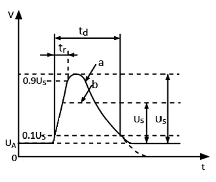
Figure 2: Test Pulses 5a and 5b (Load Dump)
Figure 3 shows the cold crank test pulse 4.
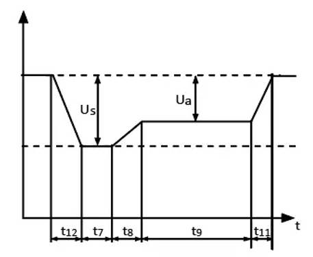
Figure 3: Test Pulse 4 (Cold Crank)
Excellent EMI Performance
The MPQ4436A achieves EMI optimization with three key features, described below:
- Switching frequency (fSW) spread technology: To improve EMI under high-current conditions, the MPQ4436A uses frequency spread spectrum (FSS) to add a ±10% frequency jitter near the fSW point. This significantly reduces peak EMI noise.
- Symmetrical pin package design: The MPQ4436A is designed in a symmetrical pin package, with a reasonable distribution for the high-frequency loop, VIN, and GND. The magnetic field can be reduced by placing the high-frequency capacitors symmetrically. Figure 4 shows the symmetrical package layout for the VIN, SW, and OUT pins.
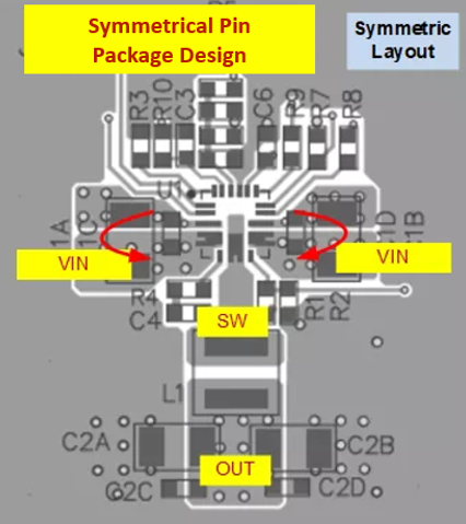
Figure 4: Symmetrical Pin Package Layout
Figure 5 shows the MPQ4436A’s package reference.
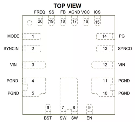
Figure 5: MPQ4436A Package Reference
The MPQ4436A can directly pass the CISPR25 Class 5 standards. Figure 6 shows the MPQ4436A’s average conducted emissions.
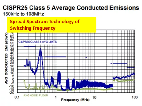
Figure 6: MPQ4436A Average Conducted Emissions
Figure 7 shows the MPQ4436A’s average radiated emissions.
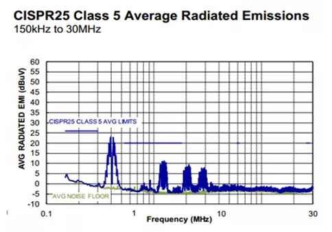
Figure 7: MPQ4436A Average Radiated Emissions
Compact Package and Excellent Thermal Performance
The MPQ4436A is available in a QFN-20 (4mmx4mm) package that eliminates the need for two MOSFETs and one sampling resistor.
With the small solution size, the MPQ4436A also has excellent thermal characteristics. Figure 8 shows that at 6A, the temperature rises by 36°C if the voltage drops from 12V to 5V.
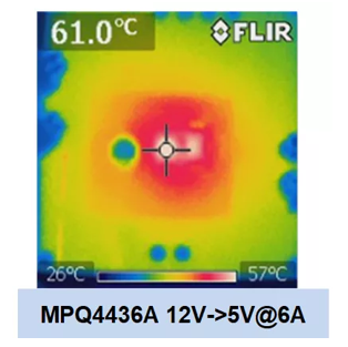
Figure 8: Temperature Rise of MPQ4436A at 6A
Figure 9 shows that the MPQ4436A’s compact package provides efficient heat dissipation.
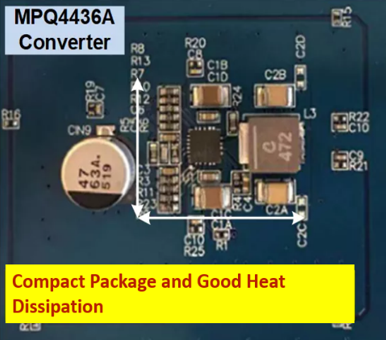
Figure 9: Compact Size of MPQ4436A
Supports Paralleling
For infotainment systems, high currents are often required for the platform design. The MPQ4436A can operate in parallel — for example, two MPQ4436A devices can operate in parallel while their outputs are 180° out of phase. While increasing the output power, the inputs superimpose one another while they are out of phase, which reduces the input current ripple and improves EMI (see Figure 10).
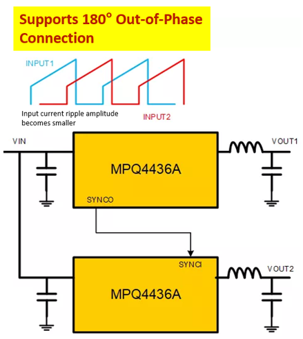
Figure 10: Two MPQ4436A Operating in Parallel
Characteristics of a Secondary Power Supply
Secondary power supplies generally provide power to high-speed communication blocks (serializers and deserializers), modulation ICs, system storage, and other peripherals in the systems. These peripherals often have specific power-on and power-off timing requirements, which can pose design challenges.
For these requirements, consider the MPQ2166A, an internally compensated, dual-channel, synchronous step-down regulator with pulse-width modulation (PWM).
Compact Package and Symmetrical Layout
The MPQ2166A is a two-in-one buck converter available in a compact QFN-18 (2.5mmx3.5mm) package. The device supports switching frequencies (fSW) up to 3MHz. This features reduces the number of peripheral inductive capacitors.
EMI is reduced by the symmetrical PCB layout (see Figure 11). EMI is further reduced because both channels can operate 180° out of phase.
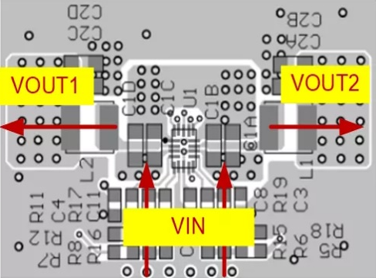
Figure 11: Symmetrical Pin Distribution of MPQ2166A
More Conducive to Multi-Rail Power Designs
Because the MPQ2166A provides separate EN, SS, and PG pins for each channel, it is simple to adjust the start-up times for each channel while monitoring each power state separately (see Figure 12).
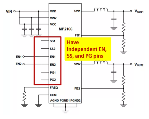
Figure 12: Separate EN, SS, and PG Pins
The MPQ2166A supports current flexibility for both channels, and can be configured for a 2A/2A or 3A/1A current distribution.
Conclusion
Power supply design is an important consideration for developing advanced car infotainment systems. This article reviewed the requirements and advantages of primary power supplies with the MPQ4436A and secondary power supplies with the MPQ2166A. Part II will address challenges for camera power supplies and USB charging.
_______________________
Did you find this interesting? Get valuable resources straight to your inbox - sent out once per month!
Technical Forum
 Latest activity 2 days ago
 2 Comments
Latest activity 3 days ago
2 Comments
Latest activity 2 weeks ago
3 Comments
2 Comments
Latest activity 3 days ago
2 Comments
Latest activity 2 weeks ago
3 Comments
Log in to your account
Create New Account