Planning for Sudden Power Failures with the MP5515

Get valuable resources straight to your inbox - sent out once per month
We value your privacy
Introduction
Power failures tend to cause a domino effect of disruptions, resulting in system failures and data loss, as well as damage to servers and equipment. This article describes how to use the MP5515 to protect solid-state drives (SSDs) against sudden power failure.
There are three main issues if an SSD experiences a power failure:
- Loss of user-written data
- Loss of flash memory conversion layer mapping information
- Increased risk for physical damage. When the SSD is subjected to strong vibrations or a sudden power failure during the reading or writing process, the SSD’s head can scratch the medium
Energy Storage and Release Management with the MP5515
The MP5515 is an input power conditioning PMIC that provides a compact, efficient backup energy management solution for enterprise SSDs, non-volatile dual in-line memory modules (NVIDMMs), and other applications. This IC includes tantalum capacitors, which are more reliable than supercapacitors. Additionally, the MP5515 can detect the circuit’s health to provide data security.
Based on the high-voltage energy storage method, the MP5515 integrates boost, buck, input current limiting, and input reverse current blocking protections, as well as power failure monitoring functions. Only a single inductor and small feedback voltage resistance are required to enable system start-up.
During normal operation, the MP5515 stores energy in high-voltage capacitors. In the event of a power failure, the device transfers energy from the storage capacitor to the bus voltage line. This energy transfer provides the system with a stable, backup power supply.
Other key features of the MP5515 include:
- Wide 2.7V to 18V operating input voltage (VIN) range
- Up to 32V of configurable storage voltage
- Up to 6A of configurable input current (IIN) limit
- 5A buck load capability
- Adjustable slew rate for the rising VB voltage (VB)
- Input current limiting with an integrated 14mΩ MOSFET
- Input over-voltage protection (OVP)
- Reverse-current protection (RCP)
- Input power failure indicator
- Backup capacitor health testing
- Integrated voltage, current, and temperature detection
The MP5515 effectively minimizes the use of standard external components, and is available in a QFN-30 (5mmx5mm) package. It also provides I2C communication and an analog-to-digital converter (ADC). We will discuss the strategic advantages of the MP5515 for energy storage and release management in detail below.
Response to Sudden Power Failure
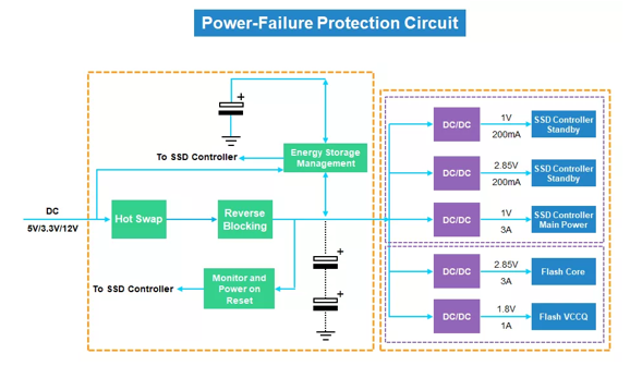
To minimize data loss, the MP5515 is designed with a shutdown detection circuit that includes a high energy density capacitor. Figure 1 shows an integrated solution with the MP5515.
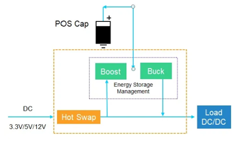
The e-fuse module continuously monitors the SSD’s supply voltage. If this power supply drops to a set threshold, this signals a sudden external power failure event, and the e-fuse cuts off the power supply circuit. The sufficient power protection window gives enough time for data to be flashed from the cache to NAND. The capacitor then forms a discharge path; once the power is turned on again, the capacitor charges quickly.
E-Fuse and Integrated, Bidirectional Buck-Boost
When the system is sufficiently powered, the diode, buck, and boost are required from the input to the output of the separation circuit. Using five (or more) FETs and diodes increases power consumption while reducing efficiency. Generally, the MP5515 only requires its integrated 14mΩ MOSFET for input current limiting.
In the event of an abnormal power failure, the MP5515’s integrated, bidirectional buck-boost converter has three FETs, which help reduce power loss while minimizing the total solution size. Figure 2 shows the MP5515’s efficiency curve in standby power mode when VB is 7.5V.
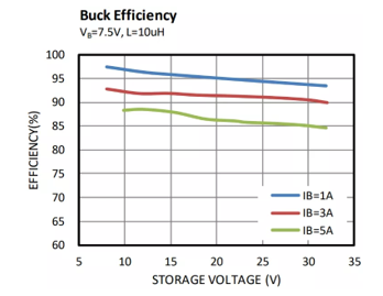
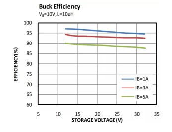
Figure 3 shows the MP5515 efficiency curve in standby power mode when VB is 10V.
Smaller Energy Storage Capacitors
According to the law of conservation of energy, when the energy storage capacitor voltage increases, its capacity is significantly reduced. The MP5515 can increase the energy storage capacitor’s voltage up to 36V. Under a consistent energy demand, the capacitance can drop to as low as 2.5mF and have a reduced ESR. Under normal conditions, the energy storage capacitor has a voltage rating of 18V and a capacitance of 8.4mF.
Highly Integrated Chip
Traditional solutions typically require matching at least four chips with complex peripheral hardware circuits and software technologies. The MP5515 provides an integrated solution using a single inductor. Figure 4 shows the typical application circuit of the MP5515.
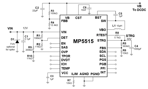
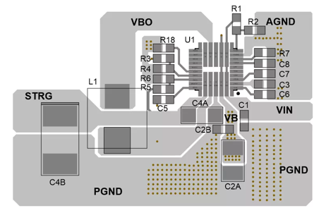
Figure 5 shows that the MP5515 requires a minimal number of external components.
Capacitive Health Detection
During SSD use, the capacitor ages and energy storage capacitance is reduced over time due to a large number of charging and discharging processes. To address this, the MP5515 integrates capacitive health testing, where an external resistor connected from STRG to RTEST discharges the energy storage capacitor. The detected results are stored in the data register for the microcontroller, and can be read via the I2C interface.
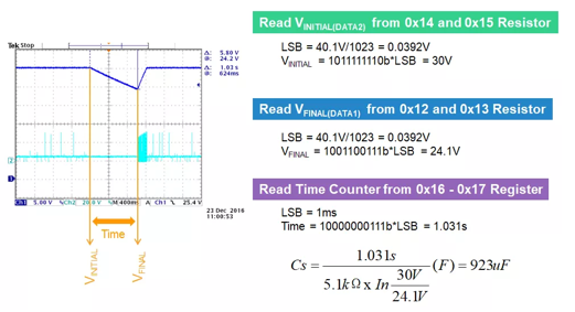
Engineers can easily derive and calculate the energy storage capacitance according to the energy conservation formula to determine whether a capacitor should be replaced. Figure 6 shows the calculations for VINITIAL(DATA2), VFINAL(DATA1), and the time counter, which are used to estimate the capacitance.
Fast Transition to Backup Mode
Buck mode supports a maximum current limit function to limit the released current. In each buck mode switching cycle, the high-side MOSFET (HS-FET) does not turn on until the inductor current drops to the valley current limit. Constant-on-time (COT) control is used when the bidirectional converter releases the energy from the storage capacitors. This minimizes the voltage drop while the device transitions from charge mode to backup mode.
Figure 7 shows the backup power release process for VIN shutdown under different bus loads (where the VB load is 1A or 5A).
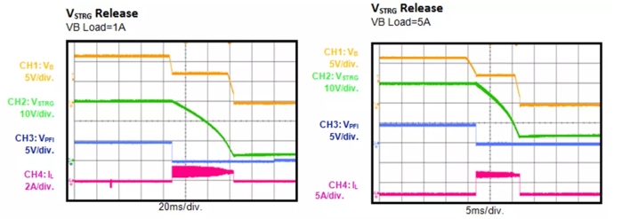
Figure 8 shows a closer look at the MP5515’s shutdown waveforms.
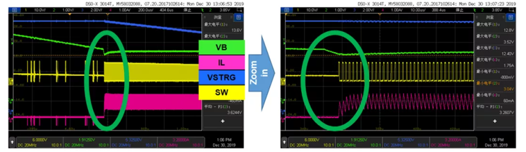
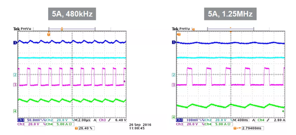
Figure 9 shows that the MP5515 also supports a wide 270kHz to 1.25MHz frequency range that supports various inductances.
Flexible Parameter Configuration via I2C Communication
The MP5515 is highly customizable through the MPS’s I2C GUI, and can implement robust features. In addition to the key features of the MP5515 that we previously discussed, these features for flexible parameter configuration include:
- Energy storage capacitor health detection
- A 10-bit ADC with voltage, current, and temperature detection
- Energy storage boost
- Adjustable buck frequency
- Input recovery control
- System status monitoring
- Interrupt mask control
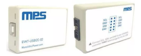
Figure 10 shows the communication kit (the EVKT-USBI2C-02).
In addition to the MP5515, MPS also offers the MP5505, MP5512, and other shutdown protection solutions.
Conclusion
Protecting SSDs against sudden power failure is critical to maintain the stable operation of many devices connected in series. MPS continues to expand on this market by launching energy storage solutions, which are customized for numerous applications that require long-term stable operation. These applications include transportation, network communications, factory automation equipment, surveillance systems, smart in-vehicle monitoring, and data centers. Explore MPS’s energy management solutions, such as the MP5515, MP5470, MP28167-A, MP5505, and MP5512, and learn how we can help power and protect your device.
_______________________
Did you find this interesting? Get valuable resources straight to your inbox - sent out once per month!
Technical Forum
 Latest activity 10 hours ago
 1 Comment
Latest activity 17 hours ago
1 Comment
Latest activity a day ago
1 Comment
1 Comment
Latest activity 17 hours ago
1 Comment
Latest activity a day ago
1 Comment
Log in to your account
Create New Account