Measuring High-Frequency, Common-Mode Current, Voltage, and Impedance (Part III)

Get valuable resources straight to your inbox - sent out once per month
We value your privacy
Introduction
This is the final part of a three-part series discussing measurement methods for high-frequency, common-mode (CM) current, voltage, and impedance using a flyback converter. Part I covered the basic principles of radiated EMI and the traditional method for measuring CM current in a flyback converter topology. Part II explored a ferrite bead solution for CM current measurement errors and how to obtain CM impedance. In Part III, we will discuss the switching noise source effect, measure equivalent voltage source, and verify the proposed measurement methods.
Switching Noise Source Effect
Based on the CM impedance measurement method from Part II, we can similarly measure the effect of the secondary switching noise source. For buck flyback converters, the primary switching voltage amplitude is higher, meaning the primary side has a significantly greater impact than the secondary side. Thus, the radiation model we established in Part I mainly relies on the influence of primary noise sources.
Figure 1 shows a comparison of CM noise generated by the primary and secondary voltage sources (VPRI and VSEC, respectively).
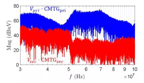
Figure 1: Comparison of the Effect of Primary and Secondary Voltage Sources
Since VPRI has a greater effect on CM noise, the values from the radiation model in Part II can be applied while ignoring VSEC as a source.
The antenna impedance and other impedances on the CM path can be obtained by removing the transformer and measuring the impedance between the primary and secondary sides, according to the CM model. Figure 2 shows this impedance measurement method.
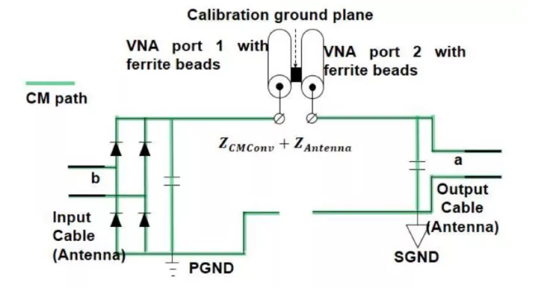
Figure 2: Impedance Measurement Method between the Primary and Secondary Sides
When measuring impedance, it is recommended to add a ferrite bead to the transmission line to avoid interference from near-field coupling. However, when the converter is not operating, the impact of coupling is unremarkable.
Figure 3 compares the measured results between ZCMTRANS and ZCMCONV + ZANTENNA. These impedances are essentially capacitive between 30MHz and 100MHz. Moreover, the transformer’s impedance at high frequencies is smaller than the sum of other CM and antenna impedances. To effectively reduce radiation, it is recommended to design the transformer such that it reduces the equivalent noise source. This method is more effective than increasing the impedance between the transformer’s primary and secondary sides.
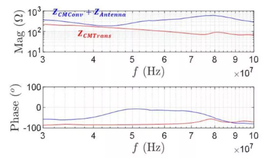
Figure 3: Comparison of Impedances
Measurement of CM Noise Voltage in Flyback Converters
For flyback converters, the equivalent voltage source between the primary and secondary sides is the main source of the CM noise between the input and output lines. However, it is not feasible to directly measure the equivalent voltage source with the oscilloscope’s voltage probe. This is due to a few reasons:
- The oscilloscope has limited resolution
- When high frequency is paired with a large amplitude (e.g. hundreds of volts), the probe can have reduced bandwidth, which makes measuring high-frequency signals more complicated
Consequently, when directly measuring the CM noise, there can be a larger relative error when the signals being measured are within the millivolt range (by up to hundreds of millivolts).
To calculate the equivalent voltage source between the primary and secondary sides, a high-pass filter must be incorporated on the oscilloscope’s front to filter out the power frequency component.
The measurement device must meet the following three conditions for accurate results:
- The measurement circuit’s input impedance must exceed the transformer’s CM impedance or the antenna impedance
- The high-pass filter’s cut-off frequency should be within a range of several MHz (when measuring frequencies above 30MHz)
- The measurement circuit’s output impedance should be significantly below the oscilloscope's input impedance
Figure 4 shows a proposed test set-up where the voltage probe is connected to the ground of the primary and secondary sides to measure the voltage difference (VGNDS) between the two sides. Then the oscilloscope is connected via a high-pass filter. Ferrite beads are placed on each test line to reduce interference.
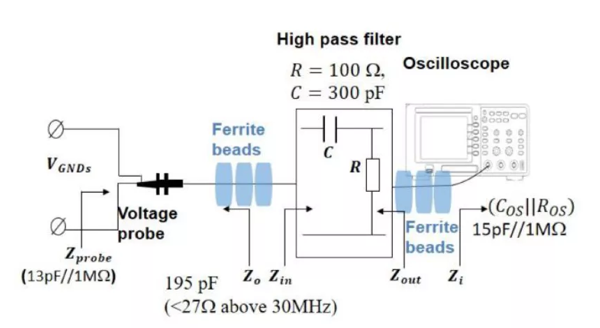
Figure 4: Improved High-Frequency Voltage Measurement Circuit by Adding Filters
To make the measured noise voltage (V’GNDS) closer in value to the noise voltage source (VCM), several ferrite beads can be added to the input and output lines to minimize the voltage division between the transformer’s CM impedance and the noise source (see Figure 5).
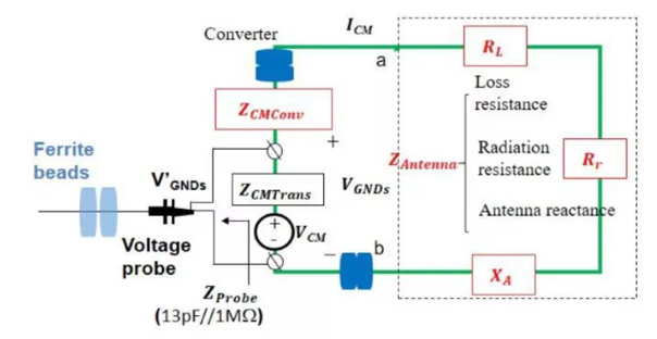
Figure 5: Improved High-Frequency Voltage Measurement Method Using Ferrite Beads
Figure 6 compares the measurement results with or without a high-pass filter. When there is no high-pass filter, the high-frequency voltage measurement is overwhelmed by noise. When there is a high-pass filter, more accurate results are obtained.
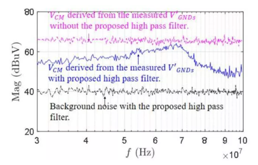
Figure 6: Comparison of CM Voltage Measurement Results with or without a High-Pass Filter
By using the measured CM voltage as well as the CM impedance obtained in Part II, the converter’s CM current can be predicted, which also verifies the CM current test method.
Figure 7 compares the results of testing coaxial and input lines when measuring CM currents, as well as the predicted CM currents. When the ferrite bead is added, the CM current result follow the predicted results. This further confirms the accuracy of these high-frequency parameter test methods.
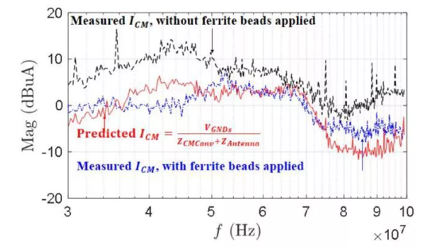
Figure 7: Comparison of CM Current Measurements with or without Test Coaxial and Input Line Ferrite Beads
Conclusion
Throughout this three-part series, we went into depth on measuring high-frequency, CM current, voltage, and impedance in a flyback converter topology. By reviewing the basic principles of radiated EMI and addressing sources of measurement errors, we successfully obtained the CM impedance and CM noise voltage in flyback converters. In summary, accurate radiated EMI analysis prevents common mistakes when measuring key parameters, including voltage, current, impedance.
For further reading on modeling and analyzing EMI problems related to CM noise, click here to learn about EMI generation, propagation, and suppression in automotive electronics.
_______________________
Did you find this interesting? Get valuable resources straight to your inbox - sent out once per month!
Technical Forum
 Latest activity a month ago
 2 Comments
Latest activity 2 months ago
2 Comments
Latest activity 2 months ago
2 Comments
2 Comments
Latest activity 2 months ago
2 Comments
Latest activity 2 months ago
2 Comments
Log in to your account
Create New Account