How to Calculate a Buck Converter's Inductance

Get valuable resources straight to your inbox - sent out once per month
We value your privacy
Introduction
In the buck circuit, the inductor design is a key element that is closely related to system efficiency, the output voltage ripple (∆VOUT), and loop stability. This article discusses how to calculate the inductance of a buck converter using the MPQ2314 as well as key parameters including the rising current of the inductor temperature, saturation current DC resistance, operating frequency, and magnetic loss.
Working Principles of Buck Topology
The working state of the upper tube (Q1) is divided into two processes: inductor charging mode and inductor discharging mode (see Figure 1). Q1 is turned on in inductor charging mode, where the inductor current (IL) rises, the inductor stores energy, and the output capacitor charges. Q1 is turned off in inductor discharging mode, where IL drops and the inductor releases energy.

Figure 1: Inductor Charging Mode and Inductor Discharging Mode
The inductance (L) can be calculated based on the relationship between the voltage and current across the inductor. This relationship can be calculated with Equation (1):
$$V = L \times dl / dt$$Where the voltage across the inductor is VIN - VOUT, dI is the peak-to-peak IL (∆IL) (typically 10% to 60% of the maximum output current, IOUT), and dt is Q1’s turn-on time, calculated with Equation (2):
$$dt = D \times t_{sw}$$With Equation (1), the state of the inductor’s energy storage when Q1 is turned on can be analyzed.
Figure 2 shows how to calculate for duty cycle, inductor current variation, and inductance.
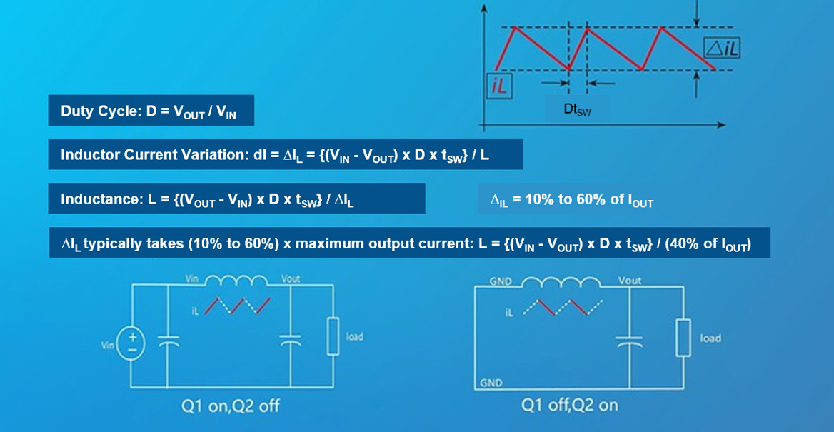
Figure 2: Calculating Duty Cycle, Inductor Current Variation, and Inductance
To balance ∆VOUT and efficiency when designing the inductor, the system typically enters continuous conduction mode (CCM) at full loads and discontinuous conduction mode (DCM) at light loads. In CCM, ∆VOUT is lower due to the inductor’s small ripple current. In DCM, the IC typically enters the frequency reduction mode, reducing the operating frequency and thereby improving light-load efficiency.
Consider an inductor’s specifications. L is measured at a certain operating frequency (typically 100kHz). L decreases as the frequency increases.
IR is the rising current of the inductor temperature, and ISAT is the saturation current. Typically, IR is slightly below ISAT. The selected IR should exceed the peak current (IPK) at full load, and also consider that the inductor cannot enter saturation during overcurrent or short-circuit conditions. Thus, IR should exceed the current-limit protection threshold defined by the DC/DC converter.
Figure 3 shows the parameters of the MPL-AY1050-100.
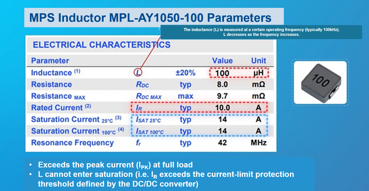
Figure 3: MPL-AY1050-100 Parameters
For the purposes of this article, we selected the MPQ2314 as the DC/DC converter, which defines the over-current protection (OCP) threshold in its specifications (typically 4A). At a full load of 2A, the inductor’s IPK is 2.58A, and the OCP threshold is 3.36A due to the upper and lower limit distribution of the OCP threshold. Select the inductor’s IR to exceed 4A with a margin greater than 20%.
Figure 4 shows the MPQ2314’s waveforms at full load as well as OCP peak current.
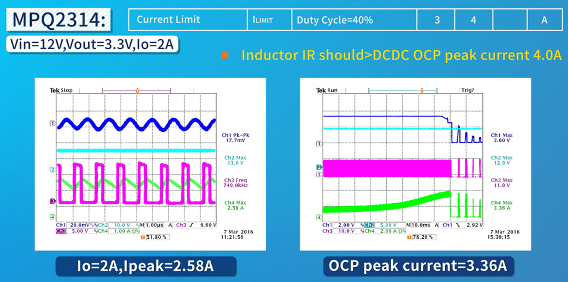
Figure 4: MPQ2314 Waveforms at Full Load and OCP Peak Current
The DC resistance (RDS, also called DCR) is directly related to the inductor’s conduction loss. When selecting the inductor, a smaller RDS results in improved efficiency and temperature rise. Copper loss accounts for the majority of inductance loss, and magnetic loss is related to the operating frequency and the magnetic core characteristics. A higher frequency leads to greater magnetic loss.
Increasing the inductance can reduce the inductor’s ripple current, which reduces ∆VOUT. However, when the inductance of this magnetic core increases, RDS increases while the saturation and temperature rise currents decrease. Therefore, it is necessary to consider this tradeoff before increasing the inductance (see Figure 5).
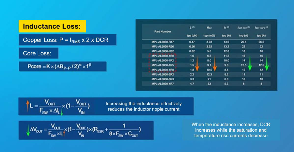
Figure 5: Calculating Inductance Loss
When selecting an inductor, approach the theoretical calculation value as close as possible, and calculate the inductor’s IPK to confirm its saturation and temperature rise currents. It is recommended to use a package with magnetic shielding, as it generates less noise and better EMC performance. Figure 6 shows a calculation example for selecting the inductance.
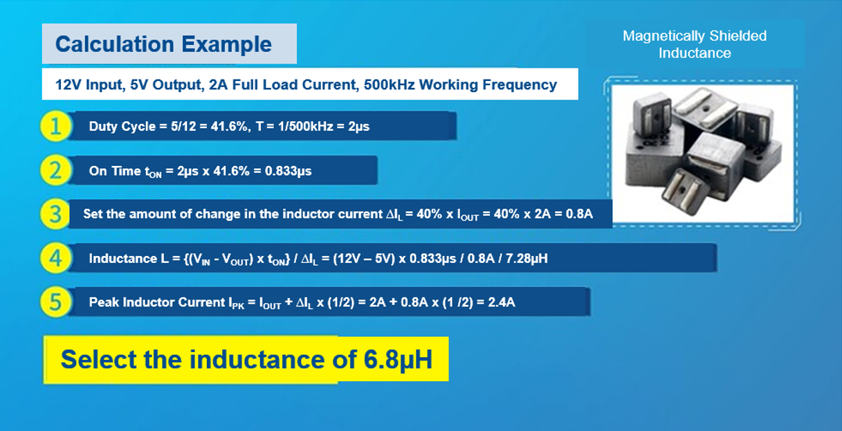
Figure 6: Calculation Example for Selecting the Inductance
Conclusion
This article laid out the steps for calculating the inductance required for a buck converter, which includes calculating for duty cycle, turn-on time, ∆IL, L, and IPK. By determining the correct inductance, system efficiency, ∆VOUT, and loop stability can also be optimized.
For more details, explore MPS's online inductor selection tool, which allows the user to easily obtain the desired inductance and add the appropriate inductor model.
_______________________
Did you find this interesting? Get valuable resources straight to your inbox - sent out once per month!
Technical Forum
 Latest activity 10 hours ago
 2 Comments
Latest activity 21 hours ago
1 Comment
Latest activity 21 hours ago
3 Comments
2 Comments
Latest activity 21 hours ago
1 Comment
Latest activity 21 hours ago
3 Comments
Log in to your account
Create New Account