How to Achieve Fast Charging with USB PD in Portable Devices
DOWNLOAD PDF

Get valuable resources straight to your inbox - sent out once per month
We value your privacy
Today’s consumers want to conveniently and quickly charge their portable devices anywhere, whether they are in a business center or shopping mall, or waiting for a flight or train. However, there are many different types of charging adapters and connectors, which can make determining which charger or chargers to have on hand confusing for the end user. If the consumer has to carry multiple different charging adapters for different portable devices (such as their phone, tablet, and laptop), they can quickly become overwhelmed (see Figure 1).

Figure 1: Input Sources and Adapters
USB Type-C (also called USB-C) connectors offer numerous benefits when compared to the above connectors (e.g. barrel jack, USB Type-A, and Micro-B), such as a reversible plug, higher power when using USB Type-C power delivery (up to 100W), dual-role power capabilities (can act as a sink or source), and higher data speeds.
Collectively, these benefits are rapidly driving consolidation toward using USB Type-C connectors in more consumer devices, and it may become the universally accepted standard (see Figure 2). This has the added benefit of drastically reducing e-waste by enabling consumers to reuse charging adapters and cables.

Figure 2: USB Type-C Connector
When considering portable devices, the higher power capability of the USB Type-C connector is very important because it means the device’s battery can be charged much faster. The previous micro-USB connector used by many portable devices allowed for a maximum power of 7.5W (5V with 1.5A). With USB Type-C, portable devices can charge their batteries at twice this power with up to 15W (5V with 3A).
Even though a standard USB Type-C power supply can provide up to 15W, the end user will rarely be able to fully utilize 15W with a 5V power supply. This is due to two main factors:
- The Type-C cable can have a maximum 250mΩ round-trip resistance, and the device’s PCB and connector typically adds about 100mΩ of resistance in series with the cable. This means a 15W supply providing 3A at 5V may only deliver up to 11.85W (15W - 3.15W) of power to the charger due to the (I x R) drop.
- Since the fully charged voltage of a single-cell battery keeps increasing year after year, a 5V supply creates a “headroom limitation” problem for the charger IC. Consider a device where the battery is in the constant voltage phase. It charges at 4.4V with a 5V USB Type-C power supply capable of 15W, and has the series resistance mentioned in the first example (350mΩ). In this case, only a 0.6V drop can exist between the power supply’s output and the battery’s input terminal. This means the maximum available current is about 1.7A (0.6V / 0.350Ω), which equates to about 7.5W of power.
To overcome this limitation, either the total series resistance can be decreased, or the power supply’s output voltage can be increased. Since the series resistance is difficult to reduce, USB power delivery (USB PD) provides a method to increase the power supply’s output voltage up to 20V in order to deliver up to 100W of power.
Even with the limitations mentioned above, standard 15W USB Type-C power supplies are sufficient for many portable devices. However, devices such as smartphones, tablets, wireless speakers, power banks, and cameras usually have batteries larger than 3000mAh, and can therefore benefit from faster charging by using USB PD. To provide the higher power output, a USB PD adapter can increase its output voltage above 5V in accordance with a command from the portable device. The maximum power a USB PD adapter can deliver is usually between 15W and 100W, depending on the voltage and current levels.
Figure 3 shows USB PD source power rules, which are outlined in the USB PD standards to ensure compatibility among different PD adapters (sources) and devices (sinks). The source output voltage must be at a 5V, 9V, 15V, or 20V discrete level depending on its power rating, while also allowing for a maximum current of 3A. It is also possible to increase the maximum current level up to 5A, but this requires a special, electrically marked cable to ensure safety.
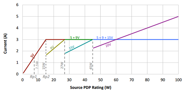
Figure 3: Source Power Rule Illustration
USB Type-C power delivery takes advantage of the Type-C connector’s ability to provide higher power by increasing the output voltage, while still being backwards compatible with 5V to enable universal charging. For example, if the sink device (such as a speaker) only requires 18W of power (9V at 2A), then any compliant USB PD adapter rated for at least 27W is guaranteed to meet this need based on the power rules. This means end users only need to carry one USB PD power supply for all of their devices, which is more convenient and cost-effective. For manufacturers, this means it is no longer necessary to bundle a power adapter in the box with their product, which also reduces cost and helps the environment by preventing e-waste.
To achieve USB Type-C PD fast charging, a PD controller IC is needed in both the portable device and power supply. The PD controller communicates with the PD adapter to determine how much power is needed by the portable device. The PD controller then checks the loading statuses and safety fault information in the portable device. In addition, a PD controller that supports dual-role port (DRP) allows the consumer to charge other devices from their portable devices, such as charging a phone from a laptop. The portable device then functions like a power bank for added convenience.
The charger IC is an important component to implement a successful USB Type-C PD fast charging system. Design engineers are looking for fast charging solutions that can:
- Simplify their designs while enabling universal charging — the ability to charge multiple battery-powered devices with different charging configurations and high input voltages
- Extend battery runtimes and use the maximum battery capacity to enable the best possible consumer experience
- Improve charge efficiency to minimize power loss within the charger IC
- Protect the battery, system, and input adapter from failures
This complete USB PD fast charging reference design includes MPS’s MP2731, a high-current switching charger, paired with a USB PD controller to create a turnkey solution (see Figure 4).
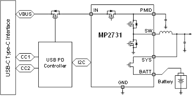
Figure 4: MPS USB PD Fast Charging Solution
The USB PD controller used in this design is compliant with the latest USB Type-C and PD standards. Controllers such as this that provide full functionality and BOM integration advantages are ideal for portable devices.
The MP2731 is an integrated buck charger IC that leverages USB PD input in charging a single-cell battery across an input voltage ranging between 3.7V and 16V. With integrated components, this buck charger gives the flexibility to charge compact, size-constrained, battery-powered devices like speakers, cameras, point of sale (PoS) systems, and other general applications.
It also provides an I2C interface to program charging configurations flexibly, and monitor the charging status and fault. An ultra-low power consumption charger IC extends the battery’s runtime during operation to conserve as much battery power as possible when the application is not in use. To support the DRP of a Type-C connector, the IC can discharge the battery to build up a regulated 5V up to 3A at its input. In this mode, the Type-C port is a source port that can power external devices like smartphones. The charging process and USB On-the-Go (OTG) operation can be monitored by the integrated 8-bit analog-to-digital converter (ADC) (see Table 1). Safety features including a fast charging safety timer, battery temperature monitoring, over-voltage protection (OVP), and over-current protection (OCP) are also critical for battery charging and system operations (see Table 1).
Table 1: Charging Parameters of the MP2731
| Parameter | Programmability |
| Charge voltage | 3.4V to 4.67V |
| Charge current | 320mA to 4.5A |
| On-the-Go (OTG) voltage | 4.8V to 5.5V |
| OTG current | 500mA to 3A |
| Pre-charge current | 150mA to 750mA |
| Termination current | 120mA to 720mA |
| ADC | VBATT, ICHG, VIN, IIN, VSYS, NTC |
| Protection | OVP, OCP, safety timer, JEITA, thermal regulation and protection |
To handle PD fast charging, the MP2731 reduces the RDS(ON) of the integrated FETs inside the switching charger to improve charger efficiency at high currents. Figure 5 shows charging efficiency curves for the PD fast charging solution, which has a charging efficiency up to 91% at a 3A charging current with 9V input.
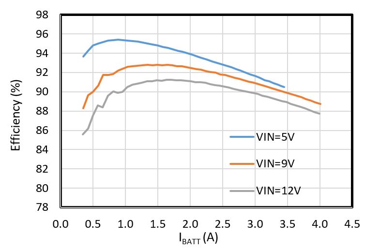
Figure 5: Charging Efficiency of MPS USB PD Fast Charging Solution
Fast charging capability can support large-capacity batteries, which can allow portable devices to support more and more features. However, portable devices typically need to be as small as possible, which drives the need for a fully integrated switching charger. The MP2731 relies on MPS’s advanced DrMOS process to integrate most components into a tiny QFN-26 (3.5mmx3.5mm) package, which saves BOM cost and PCB size.
All of the features described above help achieve an optimal USB Type-C PD fast charging solution design. USB PD fast charging offers the speed and flexibility to charge a wide range of applications, providing convenience to the end consumer.
Technical Forum
 Latest activity 6 hours ago
 1 Comment
Latest activity 3 days ago
1 Comment
Latest activity a week ago
5 Comments
1 Comment
Latest activity 3 days ago
1 Comment
Latest activity a week ago
5 Comments
Log in to your account
Create New Account