Generating and Testing Power Ripples

Get valuable resources straight to your inbox - sent out once per month
We value your privacy
The magnitude of power ripples is a common parameter to consider when designing a power supply. As a result, ripples are widely used in testing projects for power engineers. This article will discuss how power ripples are created, and how they can be tested. Note that in this article, “power ripple” specifically refers to the AC component on a power supply’s output, which has a DC voltage. Because the AC voltage is not completely suppressed, the DC voltage varies periodically.
Power Ripples
There are multiple types of power ripples, described in greater detail below.
Switching Cycle Ripples
Consider a buck circuit. This switching device turns on and off at a certain frequency. Switch ripples are generated while the device switches, meaning these ripples are generated within the switching cycle. Typically, switching ripples range between tens of kHz to several MHz (see Figure 1).

Figure 1: Switch Ripples on a Buck Circuit
Switching Noise Ripples
Due to the influence of parasitic inductors and capacitors in the circuit, the actual switching power supply produces high-frequency switching noise in the switching tube as the power supply switches on and off (see Figure 2). The switching noise frequency exceeds the switching frequency; the switching noise magnitude relates to the parasitic parameters and PCB layout.

Figure 2: High-Frequency Switching Noise Produced by Actual Switching Power Supply
Load Changes
In certain scenarios, the load current rapidly changes. Figure 3 shows how rapid current changes can cause output voltage fluctuations.

Figure 3: Output Voltage Fluctuations Due to Load Changes
In practice, many applications have stringent requirements for the power ripple. For example, radio frequency (RF) circuits, high-speed clocks, and some high-speed interfaces have requirements for the switching ripple, as well as ripple requirements across the full bandwidth.
Measuring Power Ripples
Oscilloscopes are the most common instrument used to measure ripple. There are two main considerations when choosing an oscilloscope:
- Bandwidth selection: Choose an oscilloscope that operates within the desired range. For example, do not use a 100mHz oscilloscope to test and generate data for a 500mHz ripple.
- Probe type: Common probe types include voltage probes, coaxial cables, and differential probes (see Figure 4).
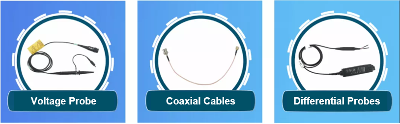
Figure 4: Common Probe Types
This article will focus on voltage probes and coaxial cable tests.
A voltage probe must be calibrated in advance. Figure 5 shows a non-attenuated 1x probe where the input impedance can be ignored. The oscilloscope is 1MΩ, and the total input impedance is 1MΩ.
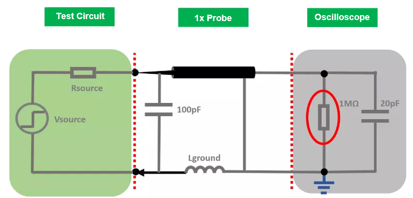
Figure 5: Impedance Characteristics of the 1x Probe
Figure 6 shows a high-impedance 10x probe where the input impedance is 9MΩ, the input impedance inside the oscilloscope is 1MΩ, and the total input impedance is 10MΩ. For 10x probes, the signal has 10x attenuation via impedance matching, and the higher attenuation ratio reduces the signal-to-noise ratio. Because the ripple is a small signal, it is better suited a 1x probe without impedance matching because the signal is not distorted.

Figure 6: Impedance Characteristics of the 10x Probe
The testing method is equally crucial. The oscilloscope probe’s ground wire acts similarly to a small inductor, and the resulting distortion ringing affects the test results. In general, it is recommended to conduct tests using the minimum tour method. If the oscilloscope’s smallest ring cannot be used, the solder wire can be used as a substitute. During testing, the probe must be directly placed at both ends of the capacitor to minimize the test circuit (see Figure 7). For the switch ripple test, it is recommended to limit the oscilloscope’s bandwidth to 20mHz to reduce the influence of test techniques and probes.

Figure 7: Directly Place the Probe at Both Ends of the Capacitor
It is also recommended to test the cumulative value of the switch ripple to verify the power supply’s stability, and to ensure that there are no oscillations. Some loads have special requirements for high-frequency noise — these loads require testing across the full bandwidth. Coaxial cables are generally recommended because the minimum ring test is too large for ground impedance and test loops relative to coaxial cables.
The coaxial cable is polarized. Figure 8 shows how coaxial cables can produce a more realistic waveform by welding to the positive and negative ends of the output capacitor.

Figure 8: Welding the Coaxial Cable to the Output Capacitor’s Positive and Negative Ends
Coaxial cables are recommended for highly reliable products that need to test ripples at higher and lower temperatures. Due to their long length, coaxial cables can be placed with the equipment used to power the IC, specifically in the high and low temperature box, without distorting the test results.
Conclusion
In this article, we reviewed basic methods to measure power ripples, and explored how to use voltage probes and coaxial cables. Power ripple generation and testing is crucial for switch-mode designs with stringent requirements, general switching ripple applications, and applications that require a suitable ripple value across the full bandwidth.
_______________________
Did you find this interesting? Get valuable resources straight to your inbox - sent out once per month!
Technical Forum
 Latest activity 2 hours ago
 2 Comments
Latest activity a day ago
2 Comments
Latest activity 2 weeks ago
3 Comments
2 Comments
Latest activity a day ago
2 Comments
Latest activity 2 weeks ago
3 Comments
Log in to your account
Create New Account