Designing Cooler Running, Multi-Channel Dynamic Automotive Lights

Get valuable resources straight to your inbox - sent out once per month
We value your privacy
Introduction
Across the automotive landscape, the push for electrification has yielded the incredible proliferation of exotic vehicles. Yesterday’s bulky, single-function lights are being replaced with newer, slender designs that wrap around a car’s front, back, or sides. The drive to go beyond traditional illumination or signaling means that tomorrow’s automotive lights will be challenged to display sophisticated patterns and algorithms, while facing unprecedented constraints in thermal management, form factor, and cost.
An example of these new products are adaptive headlights, also known as matrix headlights. These headlamps substitute old light bulbs using a matrix of numerous LEDs, which improves thermals and increases light beam control. Each LED of this matrix is controlled independently to create innovative and fascinating light designs that improve the driver’s visibility and adjust the light beam to the environment. By switching off the unnecessary light elements and keeping the rest of the area fully lit, headlamps can illuminate what drivers need to see without distracting other road users.
This article will present the challenges faced by electronic engineers when designing these new illumination products. It will focus on selecting the correct LED driver for a multi-beam headlamp, and will review how adaptive feedback control (AFC) improves thermal management. These topics will be explained through the design of a multi-beam headlight, from a high-level system overview to LED driver selection.
Matrix Headlamp
Multi-beam headlights contain three main components: LEDs, an LED driver, and a pre-regulator (buck converter) (see Figure 1).
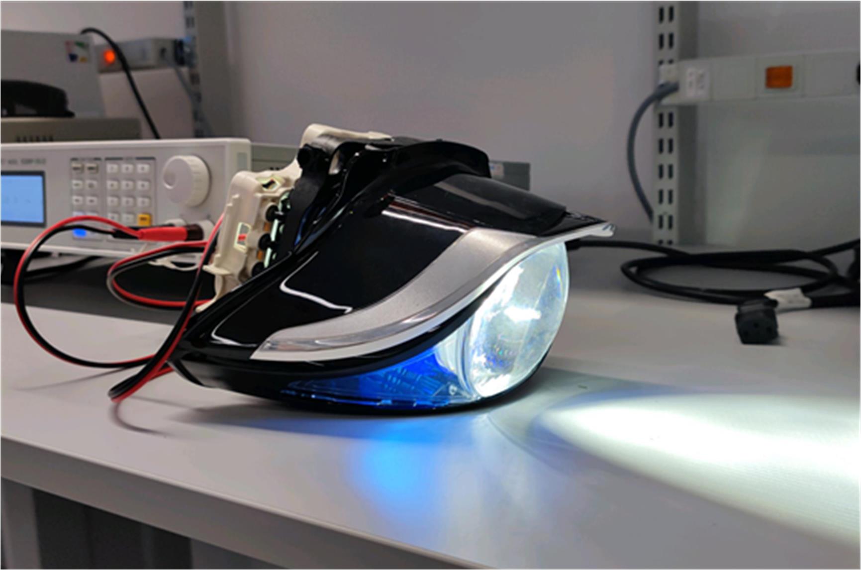
Figure 1: Matrix Headlamp
Related Content
-
VIDEO

Automotive-Grade, 16-Channel, Current-Sink Matrix LED Driver: MPQ7225
Optimized for tomorrow’s automotive LED lighting applications
-
ARTICLE
MPQ3326-AEC1 16-Channel Automotive LED Driver Applications
Learn more about our products that are meeting the needs for vehicle lighting trends
-
APPLICATION BLOCK

Headlights
Headlights remain one of the most important functional safety features in any vehicle
-
ARTICLE
Using Thermal Derating to Extend Automotive LED Life Expectancy
A simple and cost-effective solution
First, a matrix of LEDs illuminates the road layout. Due to PCB size specifications and thermal constraints, the system in this article has 84 LEDs that are distributed in 3 rows and 30 columns. Second, to adapt the light in the environment, the LEDs in the system must be controlled by LED drivers. For this example, we used six MPQ7225-AEC1 devices. Finally, since all of the headlight components are powered by the car battery, the system incorporates a pre-regulator to step down the voltage from the car battery, so that the voltage matches the LED and LED driver specifications.
Selecting an LED Driver
During headlight design, there are two main constraints that designers face: PCB size and thermals. The PCB must be as small as possible to fit into the headlamp case, which means it is vital to minimize the number of components. In addition, lighting designs must carefully consider the application thermals to avoid overheating and damaging the components. With these constraints in mind, the LED driver must be carefully selected for the system specifications.
Because the system used as an example in this article demands excellent scalability and a high number of channels per part, the MPQ7225-AEC1 was selected. This LED driver reduces the number of components, as well as the PCB space, without losing LED controllability. Specifically, the design uses six MPQ7225-AEC1 devices for a total of 14 channels per part (see Figure 2). The MPQ7225-AEC1 is a 16-channel LED driver, so it can control up to 96 LEDs individually, though this amount is not required for this design.
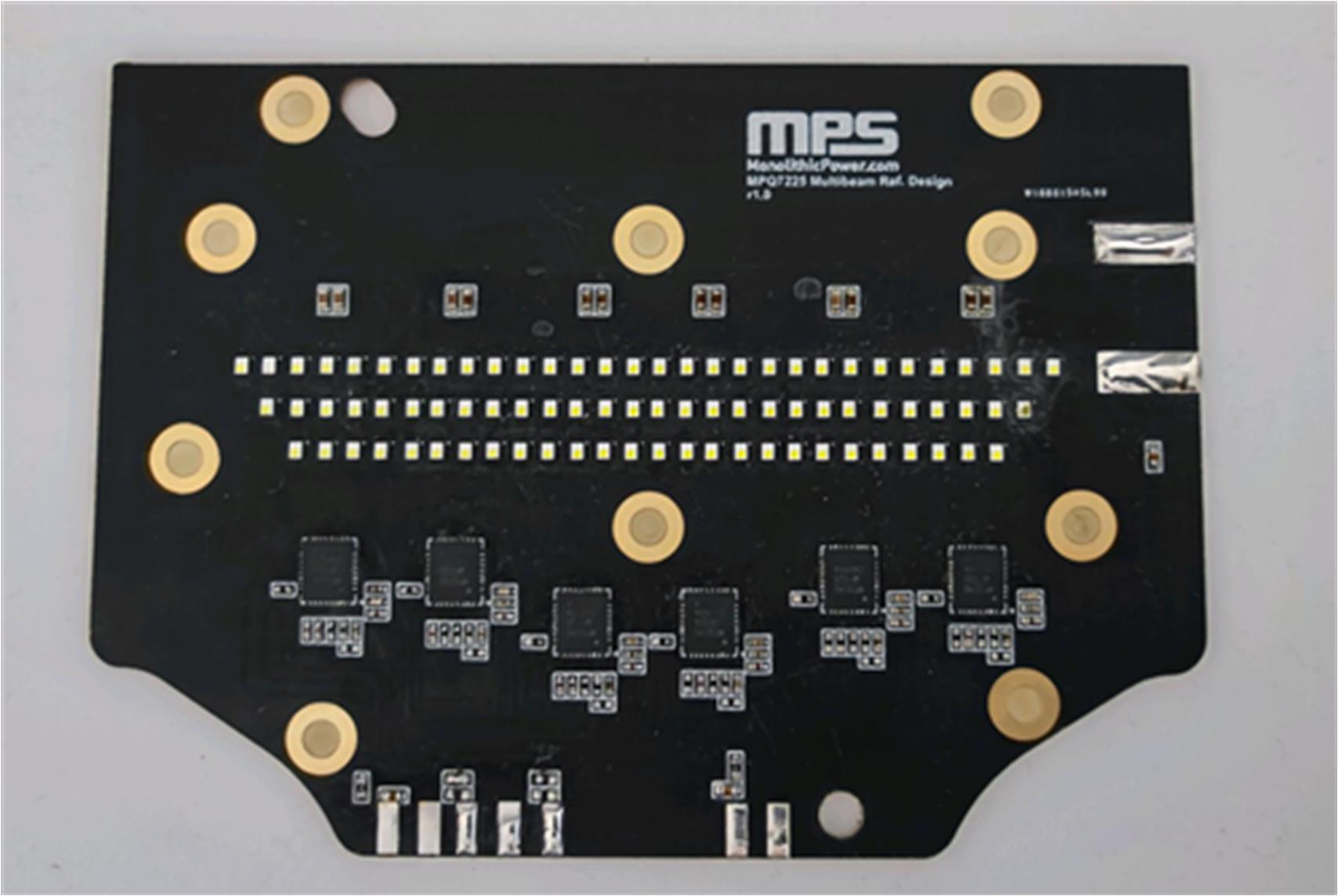
Figure 2: LED Matrix PCB
In addition to LED driver scalability, brightness is an important parameter when designing lighting parts. For multi-beam technology, it is vital to have sufficient current per channel and a limited string-to-string difference between the channels to avoid overheating certain parts of the PCB. The MPQ7225-AEC1 is an excellent LED driver for such applications since it allows an LED current (ILED) up to 200mA per channel, with an accuracy of 5% across the full temperature range. Since this design is aimed for the headlight’s high beam, the nominal current per channel was set to 200mA.
A configurable current also helps manage the temperature of lighting boards. When the board temperature rises to its maximum value, the LED driver must apply dimming techniques to reduce the LED current and, as a byproduct, its temperature. The MPQ7225-AEC1 includes two different dimming techniques: PWM dimming and analog dimming, which can be independently applied to each channel.
Figure 3 shows how PWM dimming is applied to 2 different channels. In the first channel, PWM dimming is at 50%, while channel 2 has PWM dimming at 25%. The oscilloscope captures the current that passes through these two channels, as well as how the PWM dimming differs between the channels. The PWM dimming frequency is set to 500Hz, though the configurable MPQ7225-AEC1 can also set this value to 250Hz or 1kHz.
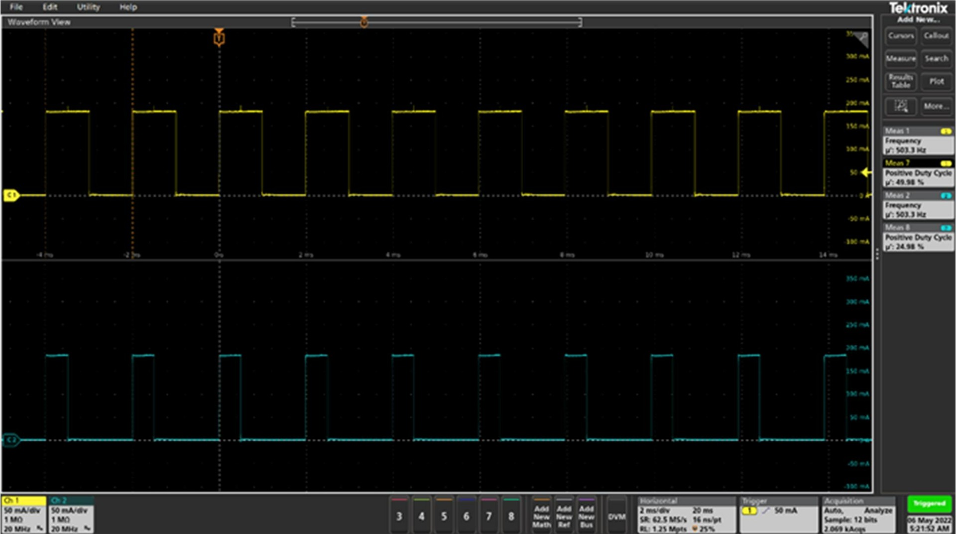
Figure 3: CH1 with PWM Dimming at 50% and CH2 with PWM Dimming at 25%
Pre-Regulator Adaptive Feedback Control (AFC)
As well as dimming, some LED drivers implement other techniques for thermal management in lighting designs. For example, the MPQ7225-AEC1 features adaptive feedback control (AFC), which adjusts the DC/DC converter’s output voltage (VOUT) based on the headroom value. This optimizes the overall system efficiency and temperature.
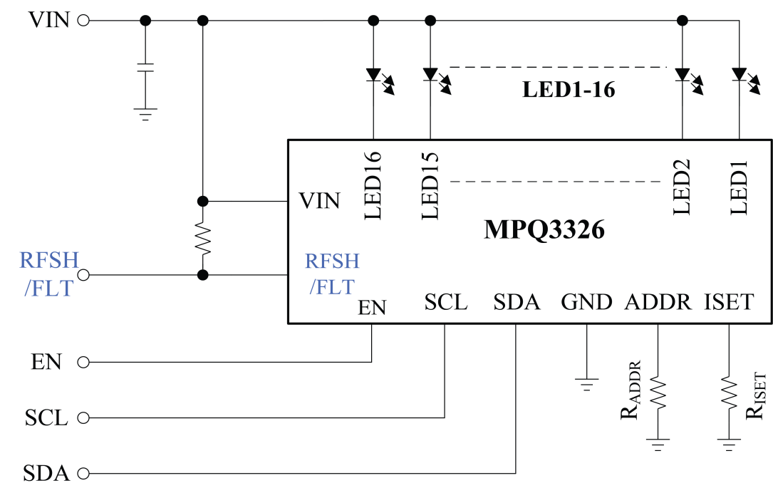
Figure 4 shows how AFC is implemented in the MPQ7225-AEC1. The voltage in each channel is sensed — if any LED output falls below 0.3V, the buck converter’s VOUT increases. If the voltage exceeds 0.4V, then the pre-regulator’s VOUT decreases.
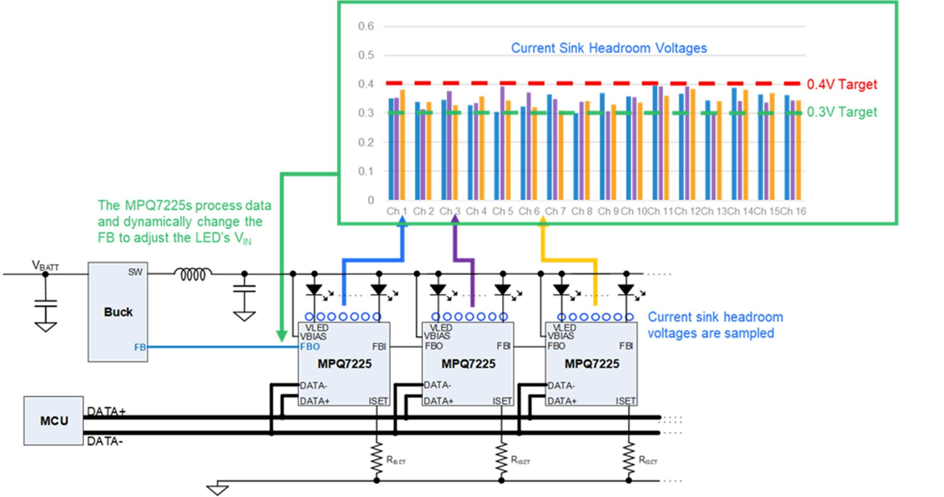
Figure 4: AFC Features
Because the LEDs’ forward voltage decreases with temperature, the headroom voltage at higher temperatures increases, which reduces system efficiency and makes the thermals worse. When the AFC function is enabled, the pre-regulator’s VOUT drops at higher temperatures to optimize efficiency and the overall system’s behavior. By using the MPQ7225-AEC1 and enabling AFC, the designer can improve thermals in lighting designs (see Figure 5).
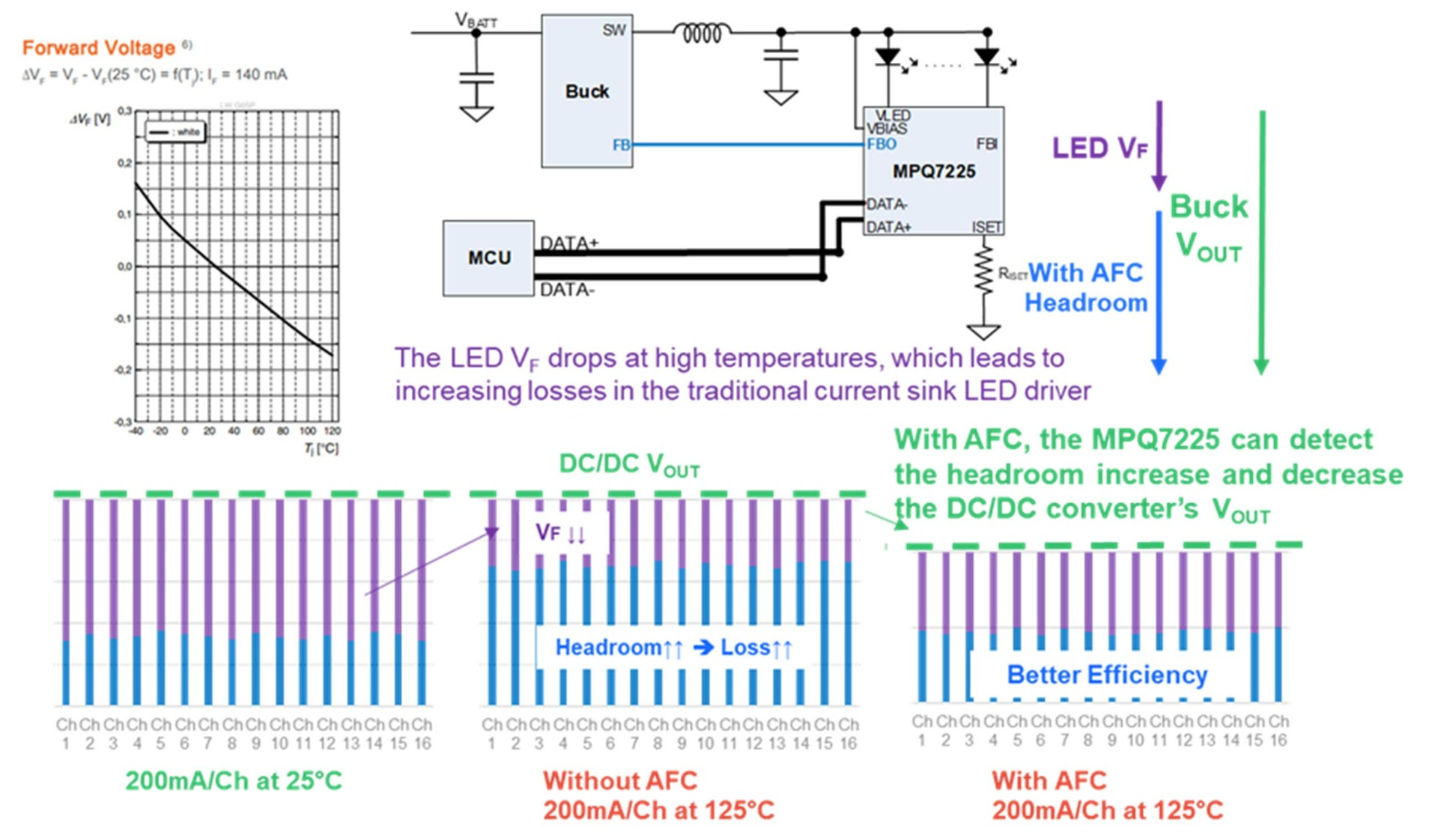
Figure 5: Relationship between LED Characteristics and Headroom Voltage
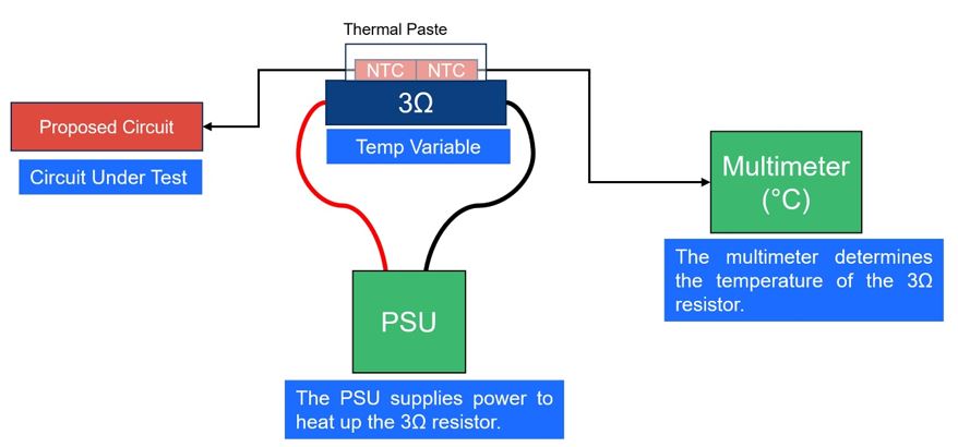
Figure 6 shows the thermal difference when AFC is applied. When VBIAS is not fixed, it changes depending on the headroom voltage, and the LED driver temperature drops by 34°C (when ILED = 200mA).
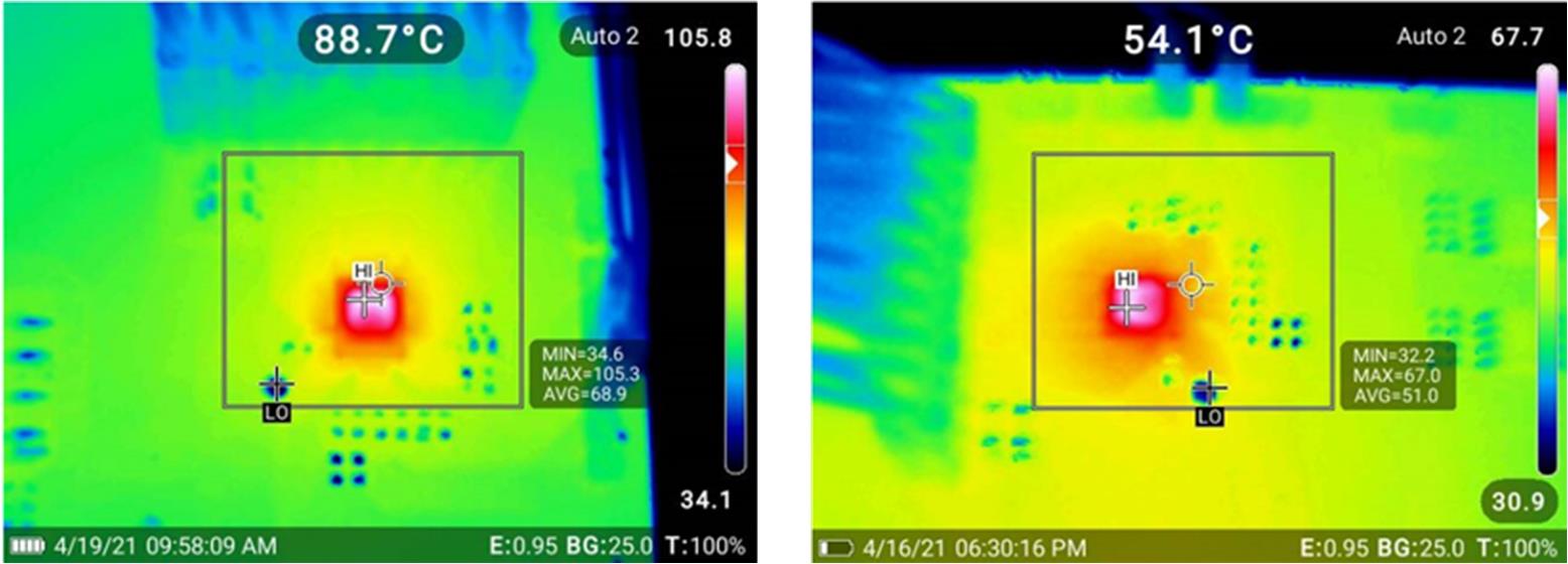
Figure 6: Thermal Performance without AFC (Left) and with AFC (Right)
Additional Considerations
For the automotive sector, it is important to make designs according to EMC constraints. Because of this, it is recommended to select LED drivers that provide options to reduce EMI. The MPQ7225-AEC1 features three EMI reduction schemes, and this presented design utilizes two of these schemes.
First, with the selected LED driver, the designer can change the slew rate of current pulses when PWM dimming is applied. In our design, the MPQ7225-AEC1 was configured to force a slew rate of 20µs. Figure 7 shows how this slew rate affects the straight current transitions by smoothing the transition and reducing spikes. Channel 1 and channel 2 of the oscilloscope capture two different channels with different PWM dimming duty cycles. The first pulse shows that when no slew rate is applied, there is a spike at the middle of the pulse. However, when slew rate is configured to be 20µs, there is no spike.

Figure 7: Comparison between a Heavy Slew Rate and a Slew Rate Of 20µs
Second, the designer can add a spread spectrum of the internal clock. When this was implemented in the design, the EMI noise around internal clock frequency (and their harmonics) was reduced.
Lastly, the LED matrix should have robust management to quickly and precisely adapt to the light design during driving time. Doing so requires fast and reliable communication between the external controller and LED drivers. Moreover, the controller board (where decisions are taken) and the LED board may not be close to one another, so communication can be corrupted due to external noise. This means that the protocol in this scenario must also be immune to noise. With that in mind, differential interfaces such as CAN are recommended. The MPQ7225-AEC1 is still an excellent choice because it supports a 2Mbps CAN compatible differential interface.
It is also important to control LED drivers through this communication protocol to configure the most important settings of the LED matrix (e.g. LED brightness and light design) without changing the hardware design. This can reduce BOM and the PCB size. The selected LED driver features a digital interface with an extensive register map. The user can switch off LEDs, modify their brightness, and monitor for possible faults that may occur during operation.
Conclusion
Multi-beam technology is an important advancement for the automotive sector — by adapting the high beam to the road layout and environment, the additional illumination allows drivers to feel more secure in low-visibility situations. However, the lighting design for multi-beam technologies presents some challenges that can be mitigated by selecting an optimal LED driver. For this article, the MPQ7225-AEC1 was selected due to its great scalability, EMIs reduction techniques, and its robust communication options. When designing a multi-beam system, thermals are a high priority, so it is recommended to introduce techniques such as AFC and dimming.
_______________________
Did you find this interesting? Get valuable resources straight to your inbox - sent out once per month!
Technical Forum
 Latest activity a week ago
 3 Comments
Latest activity 3 weeks ago
2 Comments
Latest activity 4 weeks ago
4 Comments
3 Comments
Latest activity 3 weeks ago
2 Comments
Latest activity 4 weeks ago
4 Comments
Log in to your account
Create New Account