Designing a PFC Circuit to Reduce Harmonic Distortion

Get valuable resources straight to your inbox - sent out once per month
We value your privacy
Introduction
General industrial electricity bills run much higher than residential electricity bills. From a technical point of view, the high transmission cost for industrial power results from high-power inductive or capacitive loads, which have a lower power factor (PF) than residential electrical equipment. This means that residential electricity is less expensive because it generally uses small- and medium-sized power equipment with low power consumption, high PF, and low reactive power loss.
This article will introduce the concepts of PF and total harmonic distortion (THD). Then it will review how to achieve a high PF and reduce harmonic distortion using power factor correction (PFC) circuits and PFC controllers.
Power Factor in Alternating Current
PF (λ) refers to the relationship between the active power (P) and apparent power (S), where the total power consumption is equal to V x I. λ is the ratio between P and S, estimated with Equation (1):
$$\lambda = P / S$$The relationship between reactive power (Q), S, and P can be calculated with Equation (2):
$$S = \sqrt{P^2 + Q^2}$$PF measures the degree to which power is effectively utilized. A larger-value PF means that power is utilized more effectively.
In an AC input power grid, PF can be characterized based on the actual operating waveform, estimated with Equation (3):
$$\lambda (PF) = \cos \varphi \times \frac {1}{\sqrt{1+\mathit{THD^2}}}$$The two main factors affecting PF are cos (φ) and THD. Figure 1 shows the phase difference (φ) between the input AC voltage waveform and the load current waveform.
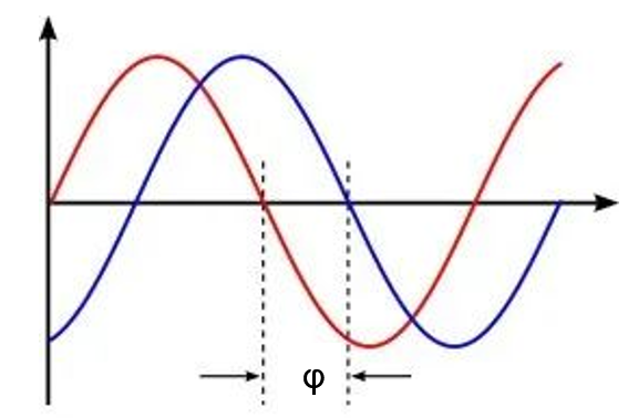
Figure 1: Phase Difference between Input AC Voltage Waveform and Load Current Waveform
Total harmonic distortion refers to the degree of input current distortion caused by harmonics. Figure 2 shows the THD between the input AC voltage and load current (see Figure 2).
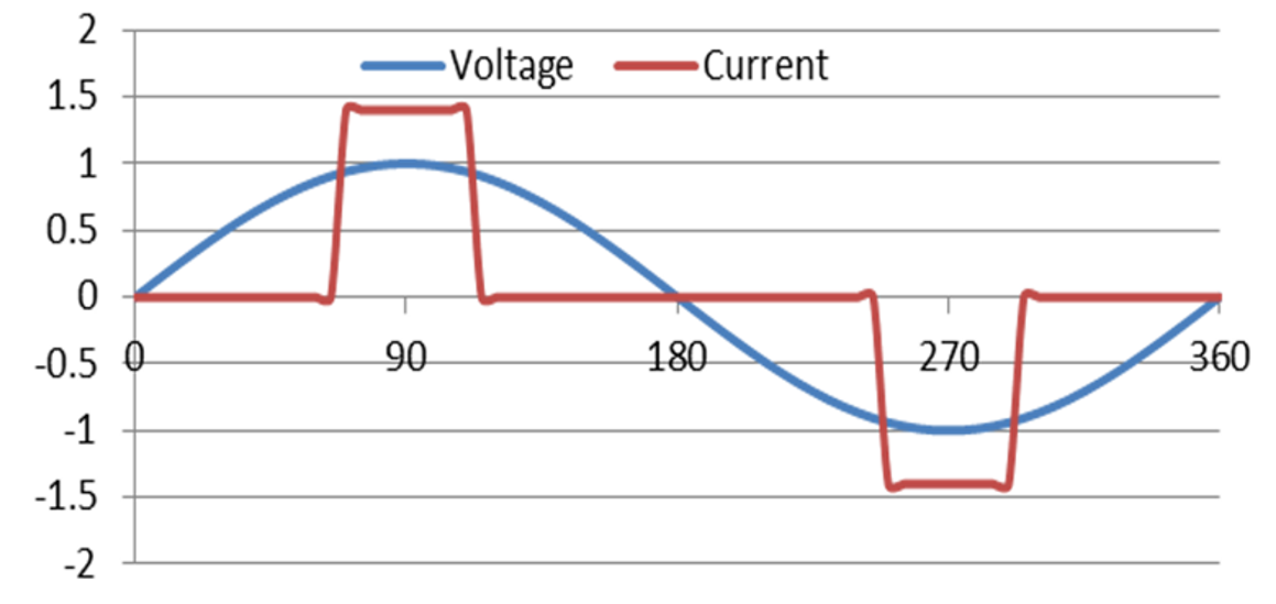
Figure 2: THD between Input AC Voltage and Load Current
-
VIDEO

High-Power MPS Solution for 3kW AC/DC PFC Totem-Pole Solution
See how MPS high-power solutions apply to an AC power supply
-
APPLICATION CATEGORY

AC/DC Power Supplies
MPS's AC/DC power supplies help build better power solutions
-
ARTICLE
Power Factor Correction (PFC)
Learn more about power factor correction
-
APPLICATION NOTE
Multi-Mode PFC + Current Mode LLC Controller
Discover MPS's HR1211 combination controller
Distortion can be calculated with Equation (4):
$$Distortion : \frac {1}{\sqrt{1+\mathit{THD^2}}}$$In the AC power grid, the harmonics are relative to the fundamental wave. Consider a 220VAC sinusoidal voltage with a 50Hz frequency that is applied to a nonlinear load. Using the Fourier series, the distorted input current waveform is made up of the sum of the components of each harmonic. THD is equivalent to the square and root of the RMS value of the second harmonic component and the RMS value of the fundamental component.
Figure 3 calculates the total harmonic distortion of the distorted input current waveform.
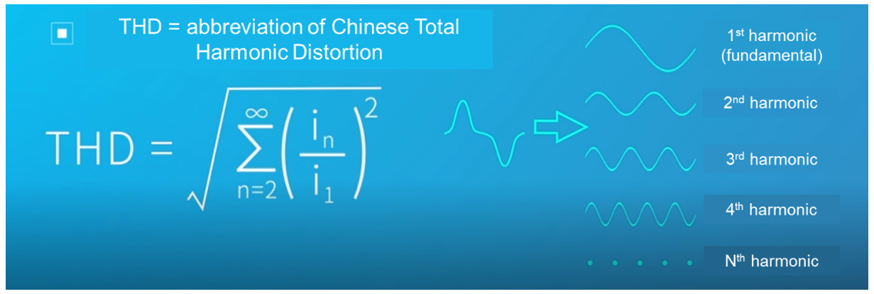
Figure 3: Calculating Total Harmonic Distortion
The greater the degree of distortion, the greater the THD value, and the smaller the PF value. To improve the efficiency of electricity consumption, international standards have been developed for the harmonic current requirements of various electrical equipment, such as IEC 61000-3-2 and EN 61000-3-2.
Using Circuits to Achieve High Power Factor Correction (PFC)
Figure 4 shows a general circuit diagram without power factor correction. There is only capacitive filtering after the rectifier bridge, which directly supplies power to the load equipment. This results in a very small conduction angle for the input current as well as poor PF. Thus, the input current obtained is a severely distorted waveform.
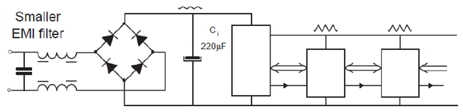
Figure 4: Circuit Diagram without Power Factor Correction
Figure 5 shows the voltage and current waveforms of the circuit diagram without power factor correction.
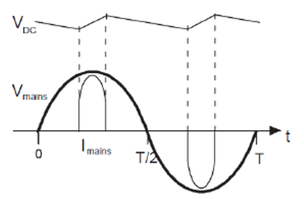
Figure 5: Voltage and Current Waveforms of the Circuit Diagram without Power Factor Correction
In the current AC/DC power supply, the active PFC (APFC) circuit is mainly used in the PFC circuit. The APFC circuit is composed of inductors, capacitors, and semiconductor switching devices. It is small in size and uses a special IC to control the current based on changes in the sinusoidal voltage waveform. The sinusoidal degree of current is high, and PF can reach 0.99, which is very close to the optimal value of 1.
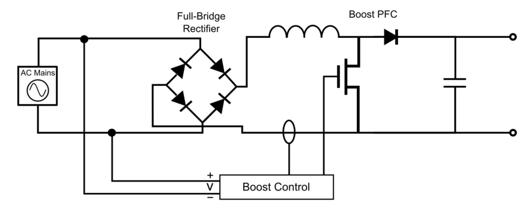
Figure 6 shows a typical boost APFC circuit that controls the inductive current waveform via a high-frequency switch.
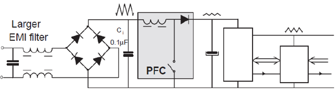
Figure 6: Boost APFC Circuit Diagram
Figure 7 shows the input current waveform and voltage waveform that are obtained from the boost APFC circuit.
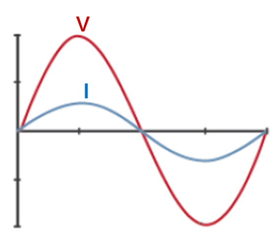
Figure 7: Input Current Waveform and Voltage Waveform of the Boost APFC Circuit
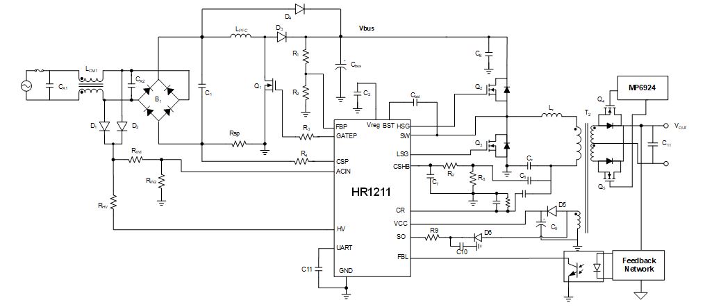
To realize the sinusoidal degree of the input current, Figure 8 shows an example of a typical boost APFC circuit. L1, D4, Q1, and C6 (in the red dotted box) form the boost APFC circuit’s main power. Meanwhile, FB is the output voltage (VOUT) feedback, MULT is the input sine wave phase tracking, and CS is the inductance current sampling signal.
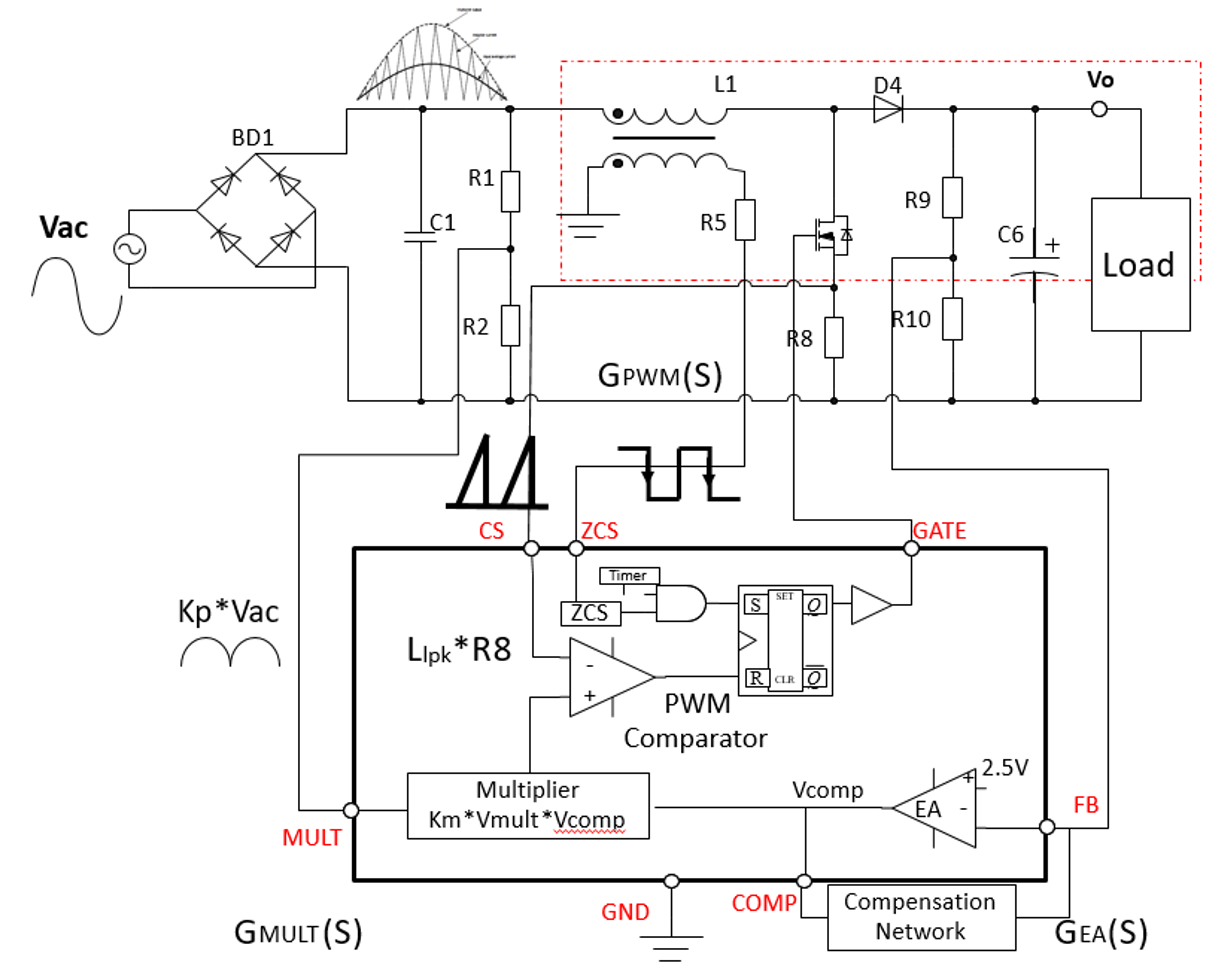
Figure 8: Boost APFC Circuit to Achieve Sinusoidal Degree of Input Current
In a switching cycle, VOUT is detected through FB, and the COMP value obtained after error amplification is multiplied with the MULT pin signal to derive a sinusoidal reference value. Then the reference value is periodically compared to the inductor current sampling signal to complete the MOSFET switch’s shutdown logic.
After the ZCS pin detects that the boost inductance current drops to 0A, the MOSFET switch’s start-up logic is triggered, which completes the switching cycle. In addition, the C1 capacitor smoothly filters the inductive current to make the input current waveform more sinusoidal and smoother. This corrects PF and obtains a high PF value closer to 1.
The APFC circuit uses a typical critical current control mode that is frequently seen in designing a power supply within 300W. For higher-power applications, select a continuous conduction mode (CCM) PFC circuit. When light-load efficiency is required, increasing discontinuous conduction mode (DCM) can effectively reduce the operating frequency while improving the switching loss and EMI.
Conclusion
In this article, we discussed the relationship between PF and THD, and obtained a high PF value using a boost APFC circuit. Integrating a PFC circuit in a power supply design minimizes total harmonic distortion and increases the larger power utilization rate, which leads to an overall lower power supply cost.
MPS offers a selection of PFC controllers to meet harmonic current requirements and improve power quality. These PFC controllers offer an integrated design with proprietary packaging technology and high efficiency.
_______________________
Did you find this interesting? Get valuable resources straight to your inbox - sent out once per month!
Technical Forum
 Latest activity a month ago
 2 Comments
Latest activity 2 months ago
2 Comments
Latest activity 2 months ago
2 Comments
2 Comments
Latest activity 2 months ago
2 Comments
Latest activity 2 months ago
2 Comments
Log in to your account
Create New Account