Designing a Multi-Phase Buck Converter with Digital Controllers

Get valuable resources straight to your inbox - sent out once per month
We value your privacy
Introduction
Over recent decades, server and computing system complexity has increased alongside power delivery (PD) requirements. This makes regulator design more challenging because it requires a tradeoff between higher efficiency and a fast dynamic response, as well as between reduced power loss and the size of the MOSFETs.
Servers require power supplies with high current, low voltages, and fast transient response, which means these devices must work at much higher frequencies than they would in other applications. To meet these needs, it is crucial to operate multiple buck converters in parallel — called a multi-phase buck converter — to drive a common load. Multi-phase buck converters are commonly used in the server and telecom industry to meet high power requirements.
Advantages of a Multi-Phase Buck Converter
A system’s fundamental frequency is effectively multiplied by the number of phases used. This allows the converter to operate at very high frequencies, which means the converter can meet higher current requirements with smaller components and less output capacitance.
A buck converter must have a fast transient response, which means it must be able to quickly transfer energy from the input to the output. For a single-phase design, this requires a small inductance, which can create large, impractical current ripples. By driving the load using parallel converters (and each branch operating with an equal phase shift), both the steady state voltage ripples and the input and output RMS currents are reduced, requiring smaller input and output capacitance.
This current ripple cancellation effectively enables the use of a smaller inductance, which also reduces transient voltage spikes. This occurs thanks to the frequency multiplication effect, where the ripple’s amplitude is divided by the N number of branches, and its frequency is N times larger. For example, a 4-phase application incurs a total inductor current ripple (IOUT = IO1 + IO2 + IO3 + IO4) that is four times smaller, and a ripple frequency that is four times larger than the individual phase (see Figure 1).
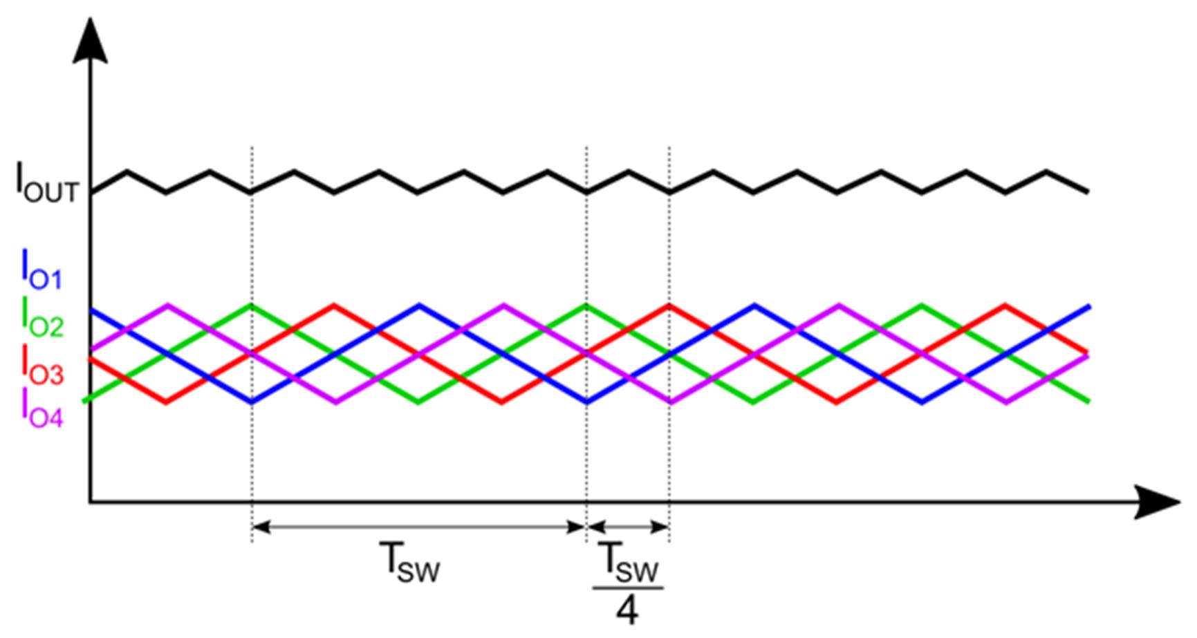
Figure 1: Total Output Current Ripple
A multi-phase converter also improves the converter’s thermal efficiency. By distributing the current across multiple phases, the power loss is also shared. This minimizes the thermal stress on each of the branches, reduces the heatsink size, and makes the total solution more cost-effective.
Challenges of a Multi-Phase Buck Converter
Multi-phase converters are key for delivering high power levels with very fast response times. However, in some applications such as server power supplies, the power required by the system varies greatly. For example, if the output current is 100A then all phases are needed to deliver the current, but if the current drops to 10A, then an excessive number of phases will dampen efficiency due to the switching losses in the additional power switches.
Implementing Digital Controllers
Digital controllers can further improve efficiency by adopting control methods, such as adaptive phase-shedding and phase control, which change the phase operation according to the load current. Designers can use these strategies to obtain a desired target efficiency across the entire load current range.
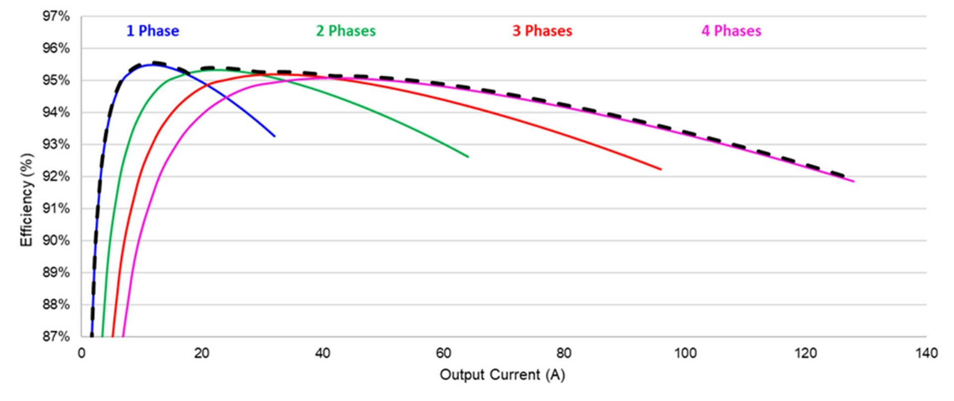
Figure 2: Phase-Shedding
Design Specifications
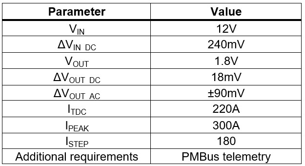
Table 1 shows the requirements for an average power rail. The input voltage (VIN) is set to 12V, which is a common value for most applications. The output current (ITDC) is 220A, and the output voltage (VOUT) is 1.8V, which is a generic value for a voltage rail in server applications.
Table 1: Power Rail Specifications
Driver and MOSFET Selection
In most multi-phase converters, each phase is designed to limit the peak current to about 40A. However, innovations within the industry have led to solutions that can handle significantly higher peak currents, with devices such as the MP86957 providing continuous current of up to 70A. This design rule is also dependent on other parameters, such as space constraints or the use of heatsinks and their thermal properties.
Implementing a Multi-Phase Converter Solution
To illustrate the benefits of multi-phase converters, this article uses a conservative current distribution target of about 40A per branch, which is implemented via a 7-phase design. This design keeps the maximum current low enough that the thermal dissipation and power loss are more manageable.
The selected switching frequency (fSW) is 500kHz. In a 7-phase design, this provides a total output ripple frequency of 3.5MHz due to the frequency multiplication effect.
The MP2965 was selected to be the digital controller since it can be configured for up to 7-phase operation. This controller uses pulse-width modulation control to tune the PWM on time in real time, according to the input and output voltages. To complete the multi-phase voltage regulator solution, this design also uses the MP86945A, a monolithic half-bridge capable of achieving up to 60A of continuous output current.
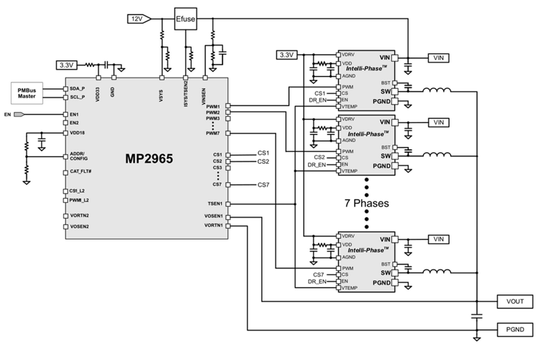
Figure 3: Interleaved Buck Converter Block Diagram)
Selecting the Output Inductor
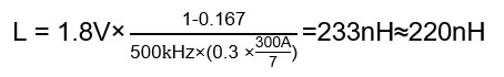
The output inductance is a vital parameter, since an excessively large ripple in the inductor current causes speed and efficiency issues. The maximum current ripple (ΔIL) for each phase must be set between 20% and 40% of the maximum phase current. For this example, a current ripple of 30% was selected, and the target efficiency (η) was set to 90%.
The inductance (L) can be estimated with Equation (1):
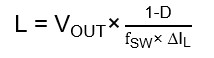
Where D is the duty cycle, calculated with Equation (2):
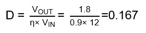
After inputting the application values, the estimated inductance (L) is found to be 220nH, as estimated with Equation (3):
Selecting the Output Capacitor
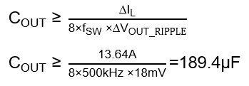
To ensure continuous inductor current operation, the minimum capacitance for a buck converter is typically selected to limit the output voltage ripple. This ripple is usually limited to 1% of the average output voltage. According to the system specifications, the voltage ripple is set to 18mV. The output capacitance (COUT) can be calculated with Equation (4) and Equation (5):
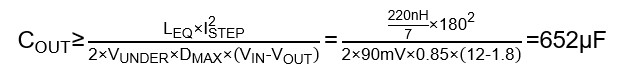
When determining the output capacitance, consider the limitations to voltage variations caused by sudden current changes in the converter. In other words, the output capacitance should also be calculated to keep the output voltage within its over-voltage (VOVER) and under-voltage (VUNDER) thresholds. VUNDER can be estimated with Equation (6):
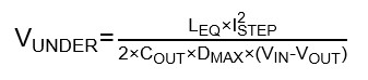
Where LEQ is the equivalent inductance (for seven phases, L / 7), and DMAX is the maximum duty cycle.
COUT for Equation (6) can be calculated with Equation (7):
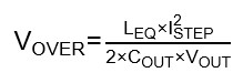
VOVER can be estimated with Equation (8):
COUT for Equation (8) can be calculated with Equation (9):
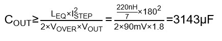
Choose the highest value between the equations above to meet all the operation requirements.
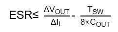
After determining the output capacitance, calculate the capacitor’s equivalent series resistance (ESR), which limits the output voltage ripple when the converter operates in steady state. The output voltage ripple can be estimated with Equation (10):
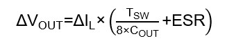
Where ESR can be calculated with Equation (11) and Equation (12):
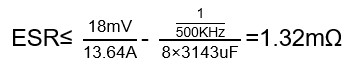
Note that the desired ESR value is quite small. To obtain such small ESR values without reducing the capacitor’s value or size, place several smaller capacitors in parallel. This sums the capacitance while reducing the ESR.
Selecting the Input Capacitor
The input capacitor provides a low-impedance voltage source for the converter and filters the input current ripple. Furthermore, adding phases to a design decreases the total input RMS current and minimizes the effects of self-heating. Figure 4 shows the normalized value of the current according to the number of phases and the converter’s duty cycle.
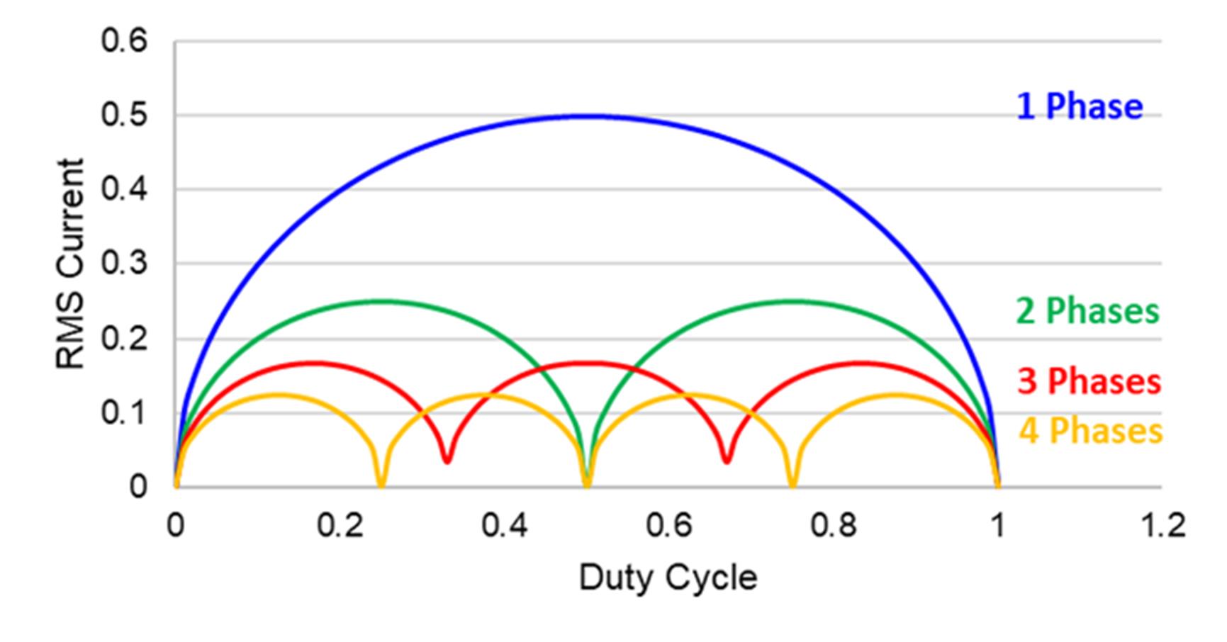
Figure 4: Normalized RMS Current as a Function of the Duty Cycle and Number of Phases
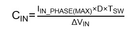
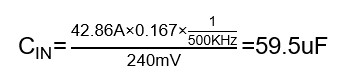
The buck converter’s input capacitance is typically selected to limit the input voltage ripple according to the application specifications. For this application, the value of ΔVIN is 240mV, and the input capacitance (CIN) can be estimated with Equation (13) and Equation (14):
Conclusion
Due to the demanding performance requirements of server systems, multi-phase buck converters are necessary in most server and computing designs in order to meet transient response requirements and be able to withstand large currents. The MP2965 dual-channel, multi-phase controller offers great design flexibility and a fast transient response with minimal output capacitors, and the MP86945A power stage integrates drivers and MOSFET to ensure high efficiency and performance.
_______________________
Did you find this interesting? Get valuable resources straight to your inbox - sent out once per month!
Technical Forum
 Latest activity 5 days ago
 3 Comments
Latest activity 3 weeks ago
4 Comments
Latest activity a month ago
3 Comments
3 Comments
Latest activity 3 weeks ago
4 Comments
Latest activity a month ago
3 Comments
Log in to your account
Create New Account