Design Considerations to Sustain Automotive Crank Conditions

Get valuable resources straight to your inbox - sent out once per month
We value your privacy
Introduction
Modern vehicles using 12V battery systems are subjected to a number of transient conditions. Some transients involve high-voltage pulses, while others may be under low-voltage conditions. Crank transients are low-voltage conditions that occur when a car engine starts, and the car battery drops several volts below its normal operating range for a brief time.
The requirements to maintain normal vehicle operation during crank conditions have become more stringent in recent years, and the need for more robust power solutions has become evident. Depending on the crank waveform — and the load that must be supplied by a specific supply rail — designing a system to meet these requirements can pose challenges to the designer. This article will explore a robust DC/DC converter that can sustain a wide range of automotive crank transients.
Designing for Extreme Starting Conditions
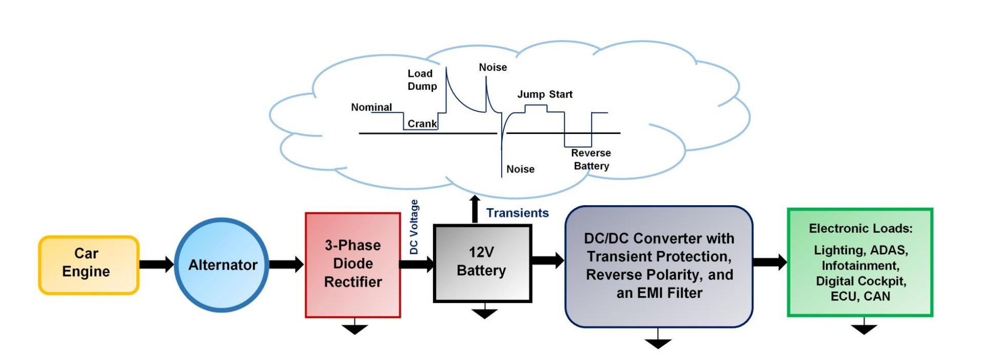
Extreme starting conditions must be considered when designing for 12V car systems (see Figure 1). Standards such as ISO 16750-2, ISO 7637-2, and Test Pulse 4 define a number of starting profiles for vehicles, including those that pertain to cold-crank conditions, warm-crank conditions, and similar waveforms.

Figure 1: Typical Automotive Electrical System
Figure 2 shows an example of a cold-crank waveform with a starting profile defined by the ISO standards.
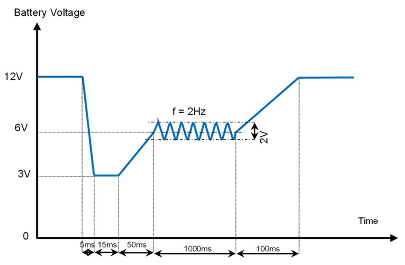
Figure 2: Example of Starting Profile for Cold Crank
The most challenging starting behavior for a vehicle is likely to occur during cold weather, when both the car battery and engine have been subjected to cold temperatures for a significant period of time. In this scenario, a high amount of battery current is needed to start the vehicle engine. A “cold-crank” condition describes when the battery voltage (VBATT) drops very low after the starter draws a high current to turn on a cold engine. Under cold-crank conditions, VBATT can drop to as low as 3V or 4.5V (depending on the vehicle’s electrical system) for 15ms to 50ms. During this event, there may be challenges if the power supply is required to regulate a particular voltage exceeding the input VBATT. For example, a 5V or 10V supply cannot be stepped down, so it must be boosted from VBATT during cold-crank conditions.
During a warm-crank condition, VBATT also drops, though typically the drop is less severe than cold cranks. In general, a warm crank waveform may drop to as low as 6V or 7V, and it does not last as long as a cold crank. This is because the engine and battery are both at a relatively warm temperature, so the starter pulls less battery current to start the vehicle. Therefore, the battery’s overall voltage drop is lower since less current is pulled.
Related Content
-
WEBINAR
From Cold Crank to Load Dump: A Primer on Automotive Transients
Modern vehicles often have complex electronics systems, which increases the challenge for power supply designers when facing harsh, dynamic transient environments such as cold crank, warm crank, reverse battery, and load dump.
-
VIDEO

MPQ8875A: Configurable, 4-Switch Buck-Boost Automotive Converter
Meet the MPQ8875A: A configurable buck-boost converter with integrated FETs and an I2C interface offering the next generation of power management for automotive applications.
-
ARTICLE
From Cold Crank to Load Dump: A Primer on Automotive Transients
This article introduces common automotive transient conditions (e.g. reverse battery, cold crank, warm crank, and load dump), and discusses the causes of these transients in addition to system design challenges.
-
REFERENCE DESIGN
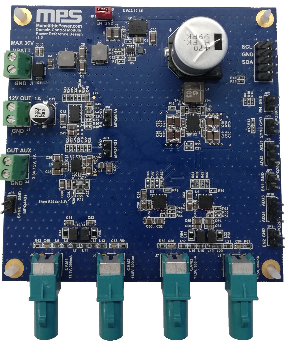
Domain Control Module - Automotive Power Stage for ADAS Applications
This reference design serves as a guideline to help users design a power supply for ADAS, using a domain control module as an example.
It is common for modern vehicles to support start/stop (or stop/start) to improve fuel economy. Start/stop is a warm-crank condition that occurs while driving, when the engine is warm. If the vehicle comes to a complete stop while the brake pedal is depressed, the engine shuts off. When the brake pedal is released, the engine is restarted. During a start/stop, critical modules in the vehicle must continue to operate without any change in performance.
Consider the example of a display control module (DCM) providing power and control to a display panel (see Figure 3).
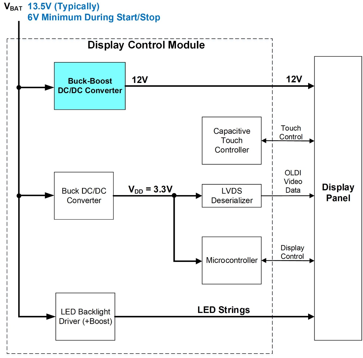
Figure 3: Display Control Module
The display panel could be a center stack display, rear seat display, or other display found in a modern vehicle. From a power standpoint, the DCM must always provide a regulated 12V supply to the display panel when the vehicle is running. 12V must also be supplied during start/stop, as the display panel cannot flicker, lose video, or stop functioning. During normal battery conditions, VBATT is between 13V and 14V. However, during a warm crank start/stop, VBATT drops to as low as 6V. To provide a constant 12V during these different conditions, a DC/DC converter must be selected that can step down (buck) a higher VBATT, as well as step up (boost) VBATT when it drops very low. To accomplish this, a buck-boost DC/DC converter is an excellent candidate to meet these requirements.
Closer Look at a Buck/Boost Converter During Crank Conditions
The MPQ8875A-AEC1 is a 4-switch buck-boost converter that is capable of meeting automotive crank waveform requirements. It supports a wide 2.2V to 36V (up to 42V load dump) input voltage (VIN) range, and has four integrated power MOSFETs. Figure 4 shows an application circuit when the MPQ8875A-AEC1 is configured to provide 12V of output at a 3A load. When VIN exceeds the output voltage (VOUT), the device operates in buck mode. When VIN < VOUT, the device operates in boost mode. When VIN is almost equal to VOUT, the device operates in buck-boost mode, and all of the switches commutate to provide 12V. For all modes, only a single inductor is required on the output to provide 12V regulation.
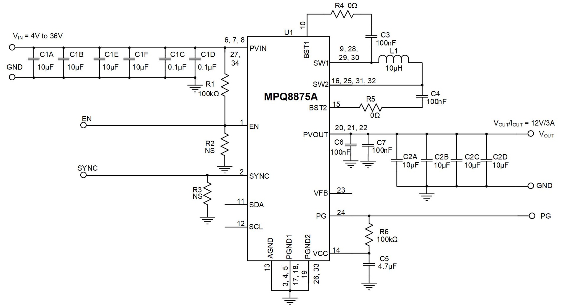
Figure 4: The MPQ8875A Provides 12V for Different VIN Conditions
A DCM was designed using the MPQ8875A-AEC1, and it was tested for start/stop (or warm crank) using a starting profile defined by ISO 16750-2, Level IV for 12V systems. Figure 5 shows its behavior during this transient event, with waveforms for VIN (in blue), VOUT (in magenta), and the inductor current (IL, in yellow). VIN is the measured VBATT input to the supply connector, which is subjected to a start/stop condition. VOUT is the measured 12V regulated output, and IL shows the measured inductor current. The load current for this test is 3A.
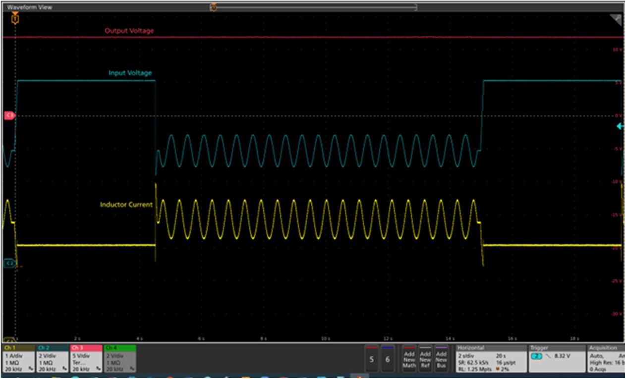
Figure 5: VIN, VOUT, and IL Waveforms for the MPQ8875A During a Start/Stop Transient Condition
During warm-crank conditions, VIN falls rapidly to 6V, where it remains for about 15ms. Then a low-frequency sinusoidal waveform, which represents an alternator ripple, occurs for several seconds; afterward, VIN returns to its nominal voltage of about 13.5V. During this condition, the MPQ8875A-AEC1 continues to regulate its 12V output without any dropout. IL increases sharply as VIN falls, and creates a 4.9A peak current that lasts for about 15ms. IL then fluctuates between 3.3A and 4.5A for about 10s. Finally, IL drops to a nominal value of 3A when VIN reaches the nominal VBATT voltage.
Selecting an inductor (L1) with a proper current rating is crucial to proper operation, as it must meet not only the peak current during a warm crank, but also the peak current during cold-crank conditions. A soft saturating inductor is an excellent choice, and it should be able to handle peak currents for the duration of the initial voltage drop of the crank waveform, as well as peaks during the sinusoidal portion. In this situation, an inductor with a minimum saturation rating between 5A and 6A range is a great start. Measuring the inductor current’s behavior during this test is a critical step in verifying that the inductor is sized appropriately. Do not overlook this step.
Conclusion
This article introduced some of the challenges when designing for automotive 12V battery transient conditions. Considerations for designing for extreme engine starting conditions, including cold cranks and warm cranks, were discussed. The MPQ8875A-AEC1 was used as an example to design a buck-boost circuit, and it was able to withstand typical cranking waveforms while providing a stable, regulated VOUT. In particular, the MOSFET and inductor current ratings are critical, especially when VIN briefly drops much lower than normal conditions. As part of the circuit design and validation, VIN, VOUT, and the inductor current should always be measured to verify proper circuit operation for all input conditions.
Additional automotive buck-boost and boost converter solutions can be found on the MPS website.
_______________________
Did you find this interesting? Get valuable resources straight to your inbox - sent out once per month!
Technical Forum
 Latest activity 4 days ago
 3 Comments
Latest activity a week ago
2 Comments
Latest activity 3 weeks ago
3 Comments
3 Comments
Latest activity a week ago
2 Comments
Latest activity 3 weeks ago
3 Comments
Log in to your account
Create New Account