Comparative Study of PFC Topologies: Interleaved Boost vs. Totem-Pole PFC Topologies

Get valuable resources straight to your inbox - sent out once per month
We value your privacy
Introduction
As more electrically powered devices are connected to the grid, the increased distortion to the electric grid can create problems in the electrical distribution network. To mitigate these issues, power supply designs require advanced power factor correction (PFC) circuitry to meet strict power factor (PF) standards.
The most commonly used topology for power factor correction is boost PFC, but the advent of wide-bandgap (WBG) semiconductors — such as GaN and SiC — have enabled the implementation of bridgeless topologies like totem-pole PFC. Furthermore, advanced totem-pole controllers such as the MPF32010 have simplified the control of complex designs such as interleaved totem-pole PFC. This article compares these three topologies when used in different applications.
Interleaved Boost PFC
Interleaved boost PFC is the most common topology for power factor correction. This topology uses a boost converter in addition to a rectifying diode bridge that converts the AC voltage to DC voltage (see Figure 1). Then the boost converter steps the voltage up to a higher value. This reduces the output voltage ripple while shaping the current into a sinusoidal wave.
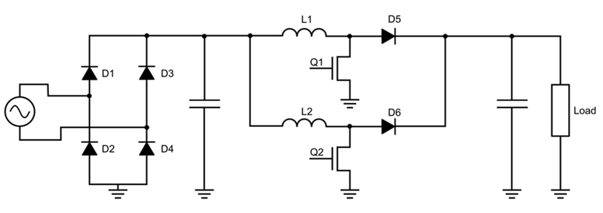
Figure 1: Interleaved Boost PFC Schematic
Power factor correction can be achieved using just one boost converter, but often two or more converters are connected in parallel, with a phase shift between the converters. This is called interleaving, which improves efficiency and reduces the input current ripple.
Bridgeless Totem-Pole PFC
New semiconductor materials for power switches — particularly silicon carbide (SiC) — have made designs that were previously limited by silicon’s thermal and electrical characteristics now viable. One of these designs is bridgeless totem-pole topology, which integrates the rectification and boost stage, and uses two switching branches that operate at different frequencies (see Figure 2).
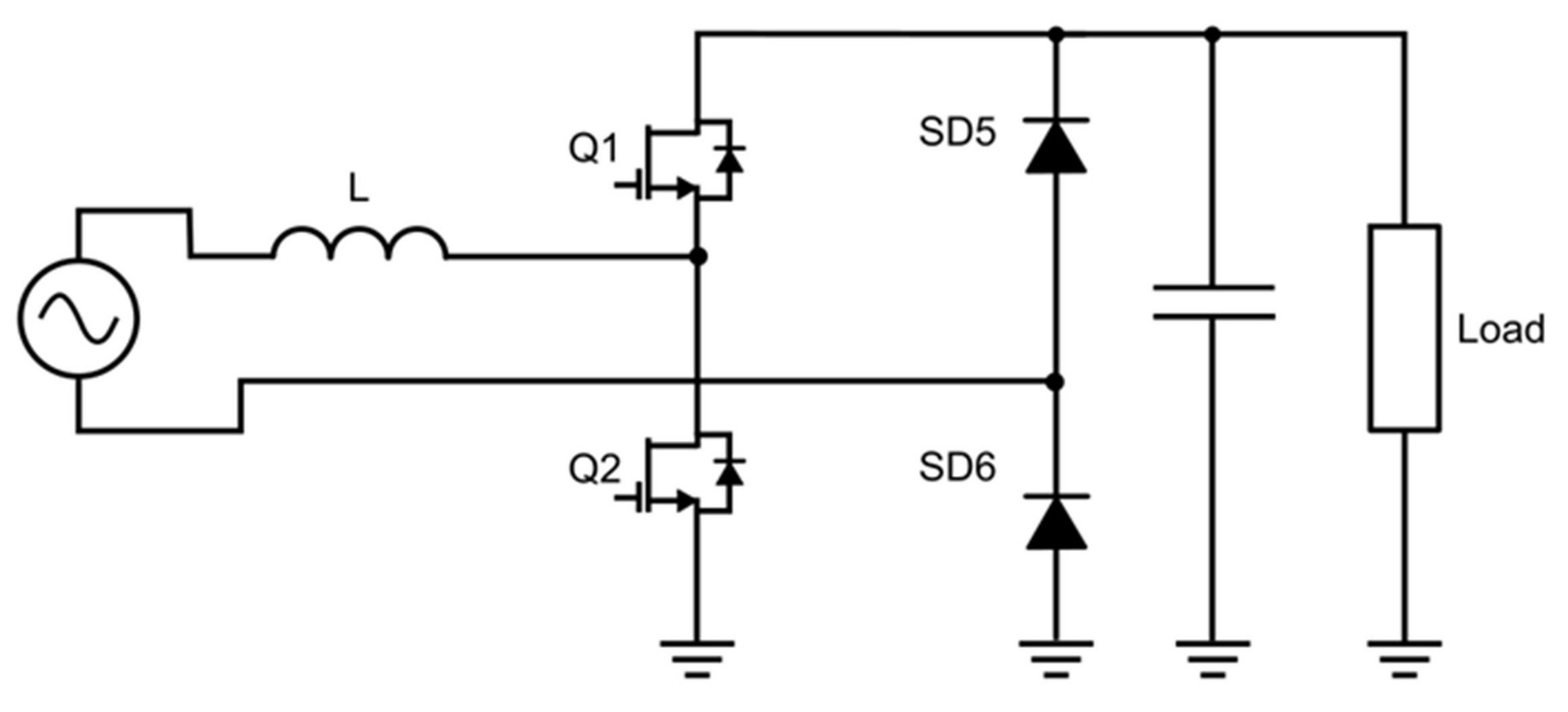
Figure 2: Bridgeless Totem-Pole PFC Schematic
The first branch, which is called the slow branch (SD1and SD2), commutates at the grid frequency (e.g. between 50Hz and 60Hz). This branch uses traditional silicon switches and is primarily responsible for rectifying the input voltage. The second branch, which is called the fast branch (Q1 and Q2), shapes the current while stepping up the voltage. This branch has to switch at very high frequencies (about 100kHz). High power switching with higher frequencies puts greater thermal and electrical strain on the switches, so WBG semiconductor devices, such as SiC and GaN MOSFETS, are required for the converter to work safely and efficiently.
This topology generally offers an improved performance compared to interleaved boost converters. However, the additional active switches make the control circuitry more complex. This issue is often mitigated with the implementation of integrated totem-pole controllers.
Interleaved Totem-Pole PFC
To improve the efficiency of bridgeless totem-pole PFC, additional high-frequency branches can be added to create an interleaved totem-pole PFC. Additional branches reduce the converter’s output voltage ripple and distribute the converter’s power requirements equally across all the branches. This minimizes both layout size and overall cost.
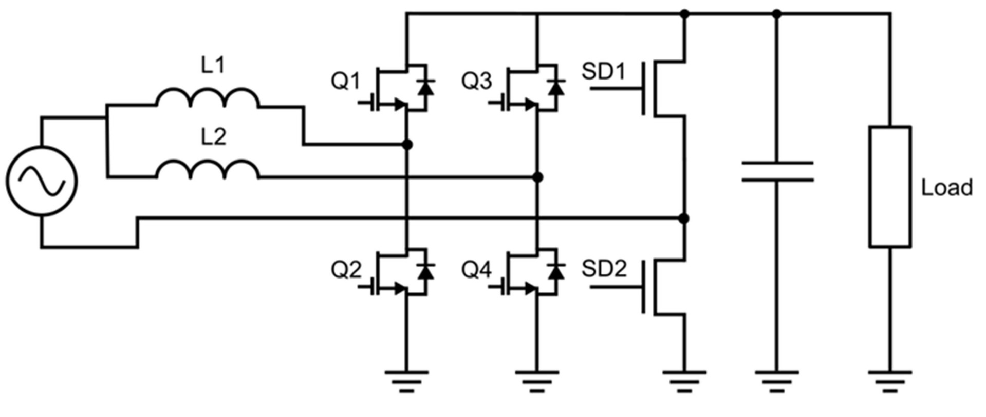
Figure 3: Interleaved Bridgeless Totem-Pole PFC Schematic
Experimental Design Comparing PFC Topologies
Operating Parameters
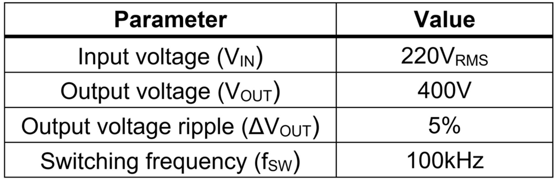
To compare topologies across different situations, a series of simulation models were developed for two power levels. To make the results comparable, the same system specifications were used (see Table 1).
Table 1: System Specifications
Comparison Parameters
Key parameters were defined to compare the different topologies. These parameters are described below.
Input current ripple (ΔIIN): ΔIIN indicates the input current’s variation, and is measured as the difference between the maximum and minimum value of the input current for a single switching period. ΔIIN can be calculated with Equation (1):
$$ \Delta I_{IN} = I_{IN\_MAX\_PK} - I_{IN\_MIN\_PK}$$Total harmonic distortion of the current (THDI): THDI is a measurement of the harmonic distortion present in the current at the input, without the presence of a filter. THDI can be estimated with Equation (2):
$$THD_I = \frac {\sqrt{I^2_2 + I^2_3 + I^2_4 + ... + I^2_n}}{I_1}$$Inductive energy index (IEI) and capacitive energy index (CEI): These indexes provide information on the converter’s inductance and capacitance requirements per unit of power (see Equation 3 and 4). These parameters are strictly related to the final size and cost of the components. IEI can be calculated with Equation (3):
$$IEI = \frac {\sum_{i=1} ^{N} \frac {1}{2} L_i \times (I^{PK}_i)^2}{P_{NOMINAL}}$$CEI can be estimated with Equation (4):
$$CEI = \frac {\sum_{i=1} ^{N} \frac {1}{2} C_i \times (V^{PK}_i)^2}{P_{NOMINAL}}$$Total switching power index (TSP): TSP compares the voltage and current stress of the converter’s semiconductor devices per power unit (similar to a silicon equivalent area). TSP is highly related to the final cost of the silicon devices in the converter. TSP can be calculated with Equation (5):
$$TSP = \frac {\sum_{i=1} ^{N} V^{PK}_i \times I^{PK}_i}{P_{NOMINAL}}$$Efficiency (ƞ): Efficiency compares the amount of energy lost by the power factor correction circuit. It is calculated as the ratio between the input power drawn by the circuit and the power available at the output (see Equation 5). Efficiency determines which topology experiences the least power loss. Efficiency can be estimated with Equation (6):
$$ \eta = \frac {P_{OUT}}{P_{IN}} = \frac {U_{OUT} \times I_{OUT}}{U_{IN\_RMS} \times I_{OUT\_RMS}}$$Totem-Pole PFC vs. Interleaved Boost PFC Results
The first test simulated all three topologies for a 300W application. This power level is often used in power supplies for computers. The second test was executed at 3kW, which is a much higher power level, often used in applications such as EV charging.
Comparisons between topologies can yield general conclusions about each topology. However, the performance of these designs does largely depend on the selected devices and the operating parameters they are subjected to. Therefore, designers must carefully consider which design to implement, and take great care in optimizing the design for their application. To illustrate this, a power losses analysis has been carried out considering only device losses, while similar devices are used for all topologies.
Power Advantages of a Totem-Pole PFC
When comparing the topology structure, the first key aspect is that totem-pole PFC does not include a rectifying bridge, which reduces the number of switching devices. The diode bridge in the boost converter is always conducting, so conduction losses are a very important factor for this topology’s efficiency. At low power, currents in the converter are relatively small, so the majority of power loss is produced during the switching operations. This is why boost and totem-pole PFC topologies have similar efficiencies for 300W applications (see Figure 4). For simplicity, the comparison of efficiency has been made between the interleaved boost and totem-pole converters, since there is little difference between losses in the traditional and interleaved totem-pole designs.
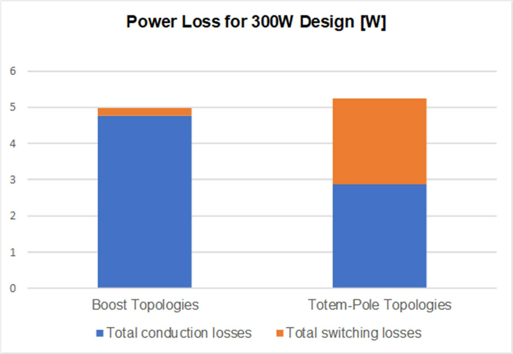
Figure 4: Power Losses in 300W Design
When operating at 3kW, the current in the circuit is significantly higher, which incurs significant conduction losses in boost topology due to the high equivalent resistance in the rectifier’s diodes. Because of this, totem-pole PFC is much more efficient in high-power applications (see Figure 5).
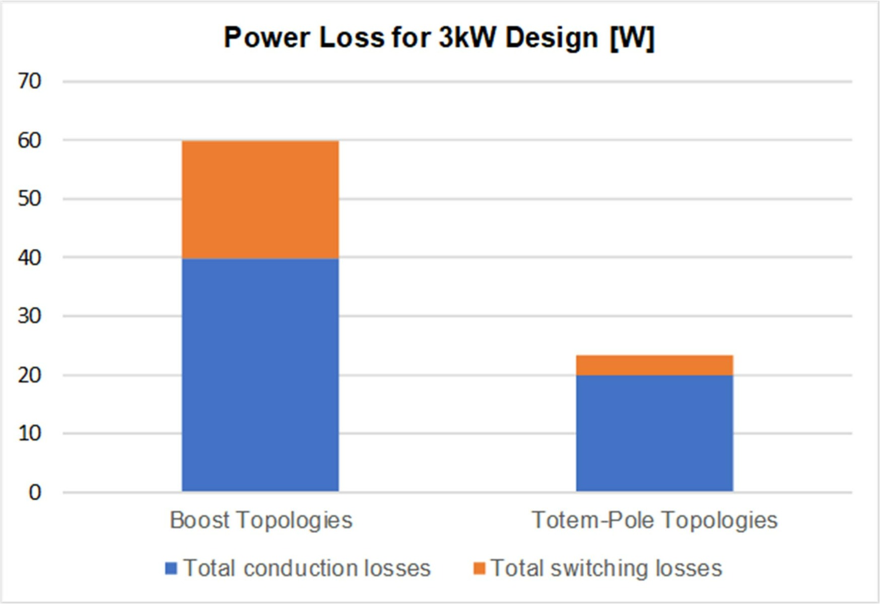
Figure 5: Power Losses in 3kW Design
Improved Efficiency of Interleaved Boost and Totem-Pole PFC
Another crucial aspect to compare boost and totem-pole PFC topologies is the operating mode. Totem-pole topologies usually operate in continuous conduction mode (CCM), whereas interleaved boost topology operates in critical conduction mode (CrCM). CCM operation significantly reduces the inductor current ripple and THDI, while CrCM requires a much smaller inductance and results in a lower inductive energy index (IEI) (see Figure 6).
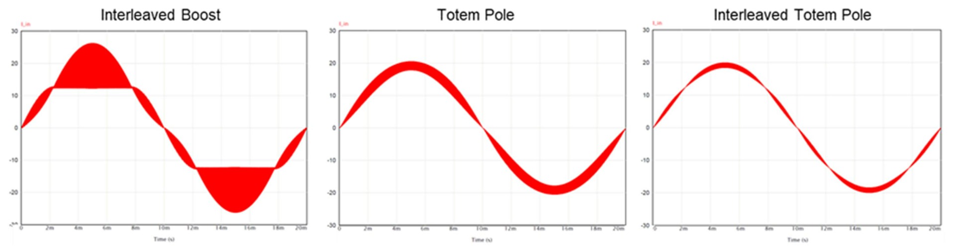
Figure 6: Input Current Simulation Results
However, the increased THDI means a boost PFC requires a large input filter to meet power quality requirements. This undercuts the benefits (reduced cost and size) gained by losing an inductor. In addition, the current across the switches is much larger in CrCM than in CCM, which adds voltage and current stress to the switching components (see Figure 7).
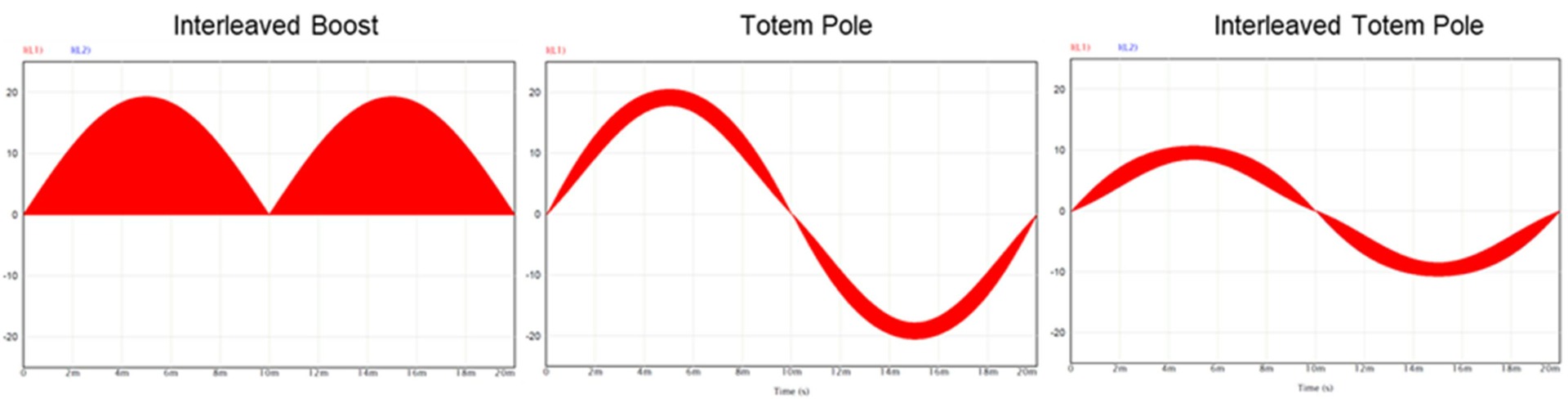
Figure 7: Simulation Results of Current through the Inductors
Connecting multiple converters in parallel improves performance by distributing the current stress across several phases. By itself, a single, non-interleaved boost converter would not be able to match the efficiency and performance of totem-pole PFC. However, by interleaving several boost converters, performance drastically improves, which makes interleaved boost topology a valid option for mid-range power applications, such as the 300W example shown above (see Figure 8).
At high power, even interleaved boost converters struggle to match the efficiency of totem-pole topologies. Furthermore, for applications at 3kW or greater, even totem pole converters benefit from interleaving. Dividing the current requirement across two branches allows the inductance of each branch to be halved, which relaxes the power switch requirements while simultaneously reducing the input current ripple.
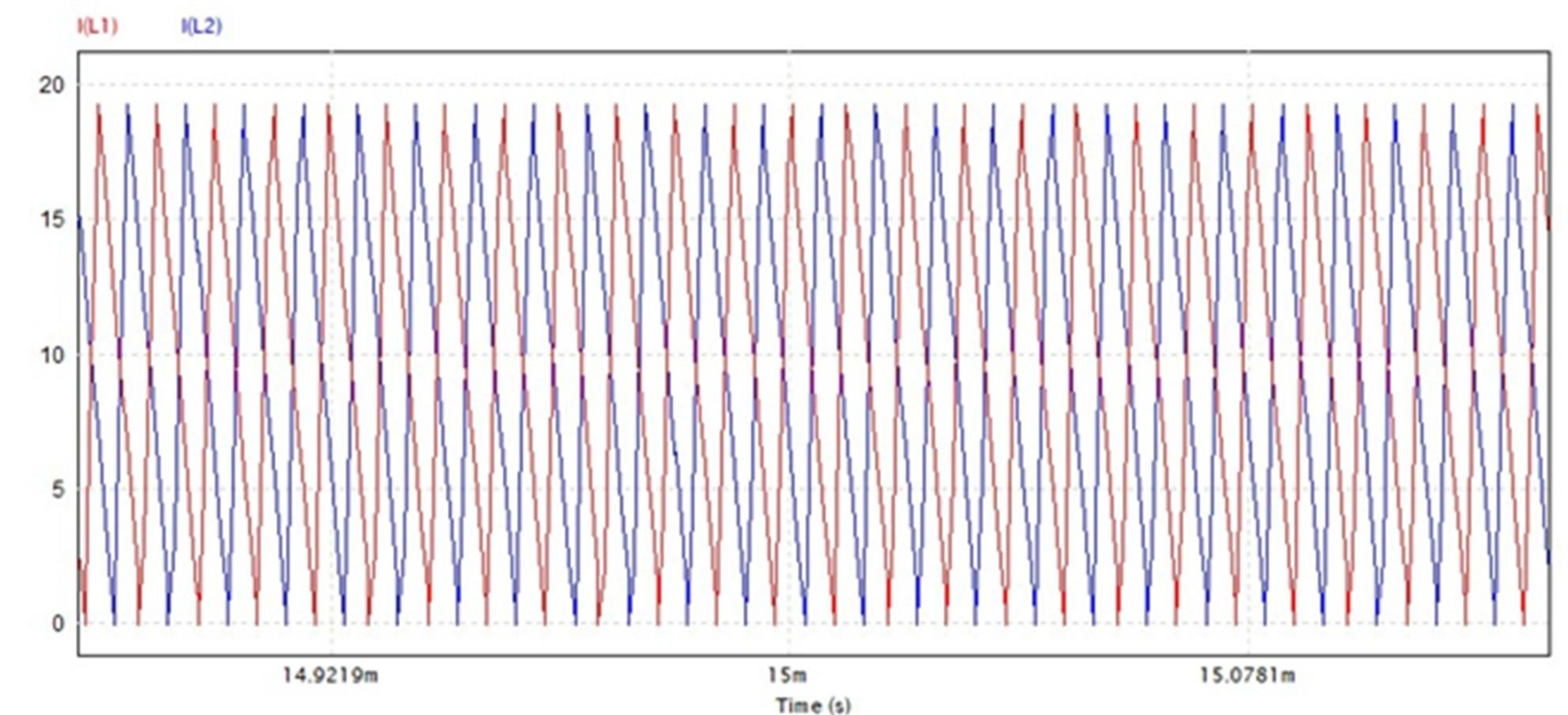
Figure 8: Inductor Current in Interleaved Boost PFC
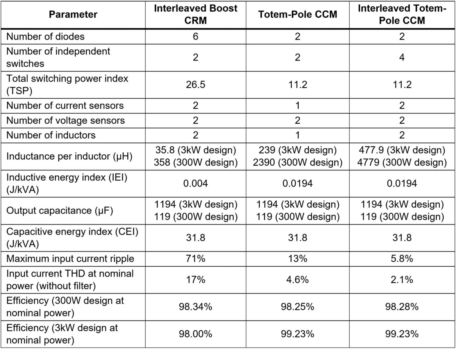
Table 2 summarizes the different parameters between the three PFC topologies.Table 2: PFC Topology Comparison Simulation Results
Conclusion
This article used simulations and key comparison parameters to illustrate the main characteristics of interleaved boost, totem-pole, and interleaved totem-pole PFC topologies, with the intent of helping designers select the best topology for their application.
The simplicity of boost PFC topology has made it the go-to solution for most designers. However, boost PFC suffers from lower efficiency in high-power applications. In these cases, a totem-pole PFC topology may be preferable despite the added complexity. The introduction of integrated totem-pole controllers such as the MPF32010 have greatly simplified the implementation of totem-pole PFC converters.
_______________________
Did you find this interesting? Get valuable resources straight to your inbox - sent out once per month!
Technical Forum
 Latest activity 21 hours ago
 1 Comment
Latest activity 16 hours ago
2 Comments
Latest activity a day ago
3 Comments
1 Comment
Latest activity 16 hours ago
2 Comments
Latest activity a day ago
3 Comments
Log in to your account
Create New Account