Brushed DC Motors and BLDC Motors: Parameters, Operation, and DC Motor Drivers

Get valuable resources straight to your inbox - sent out once per month
We value your privacy
Introduction
DC motors are machines that convert electrical energy to mechanical motion, and their versatility means they can be used in small household appliances and industrial machinery. DC motors rely on electromagnetic interactions. They are simple, efficient, and versatile.
This article will describe the components, operation, parameters, and calculations that are pertinent to two common types of DC motors: brushed DC motors and brushless DC (BLDC) motors, in addition to introducing motor drivers that can be used with these solutions.
DC Motor Parameters
Whether brushed or brushless, DC motors have a few key parameters that must be detected, monitored, and even calculated to determine which motor is best suited for an application.
Figure 1 shows a summary of motor driver parameters, which are described in greater detail below.

Figure 1: DC Motor Parameters
1. Voltage: Voltage is the electrical potential difference that is applied to the motor. A motor’s voltage is crucial because it is related to other parameters, such as the motor’s speed, torque, and output power (POUT). For example, a higher voltage results in a faster speed. DC motors can also be controlled by their voltage, since adjusting the voltage can change the motor’s speed and even reverse the motor’s direction. Reducing the voltage slows down the motors; when the voltage drops to zero, the motor stops.
Every motor has an operating voltage range. It is recommended to maintain the motor’s voltage within its operating range to ensure that the motor operates effectively and safely.
2. Current: When a voltage is applied, current flows through the motor. The current is linearly related to torque; when the voltage is constant, increasing the torque increases the current. While raising the current can also increase POUT, it is vital to keep the current within its operating range. An over-current (OC) condition can overload the motor and result in overheating.
Current does not impact the motor’s speed as much as voltage, but it can still be used to fine-tune the motor’s speed.
3. Torque: Torque is a measurement of the motor’s rotational force. A motor’s rotational force is critical, with the maximum torque being one of the main parameters to consider when selecting a motor. Torque must be sufficiently high to overcome a motor’s mechanical resistance or load, whether this includes running a conveyor belt or rotating heavy machinery.
When a motor begins to run, it requires a high torque to accelerate; in addition, it has a deceleration torque that must be able to slow down the motor within the appropriate timeframe. Certain applications such as MRI machines require a motor with a high continuous torque, while applications such as robotic arms require a motor that can supply bursts of incredibly high torque.
Torque can be calculated with Equation (1):
$$T=K \times I$$Where I is the current, and K is the motor’s specific torque constant.
4. Speed: A motor’s speed measures how quickly the motor rotates, and is generally noted in rotations per minute (rpm). Speed is inversely proportional to the load applied to the motor. If the load increases, the motor slows down. A motor’s speed can be increased by increasing the motor’s voltage.
A motor may need to operate at certain speeds to optimize efficiency. Because the speed can be adjusted by changing the motor’s load or voltage, DC motors are popular for applications that require varying speed, such as conveyor belts and fans. In many applications, it may be necessary for a motor to maintain a particular speed. In this scenario, a feedback controller (e.g. an encoder) can be used to ensure that the speed remains constant regardless of changes to other parameters or the load.
For DC motors, speed and torque are related such that motors can produce higher torque at lower speeds, and lower torques at higher speeds.
5. Efficiency (η): A motor’s efficiency measures how effectively a DC motor converts electrical power into mechanical power. A high efficiency means a motor uses less electrical energy to accomplish a task, which is ideal for battery-powered devices and electric vehicles. More efficient motors also cost less to power and maintain. Because they produce less heat, they are more likely to prevent overheating and can last longer.
Certain markets have efficiency standards that must be met for a motor, whether for safety or environmental concerns. Although a more efficient motor may have a higher initial cost, it will function for longer and cost less throughout its lifecycle.
Brushed DC Motors: Components and Operations
Brushed DC motors are cost-effective devices for a wide range of applications that require rotational movement. Brushed DC motors are comprised of four main parts. Figure 1 shows all the components of a brushed DC motor, and the main components are described below.
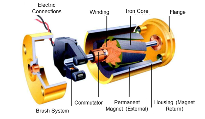
Figure 1: Brushed DC Motor
The part of a brushed DC motor that moves is called the rotor. The rotor is a cylinder that has coils of wire wound around it, and it is connected to the output shaft. The coils attached to the rotor can rotate, which drives the shaft.
The stator is a stationary component connected to the rotor. While the rotor is surrounded by coil wire, the stator consists of a set of permanent magnets or field windings.
The commutator is mounted on the rotor shaft and is connected to the windings. The commutator changes the direction of current that flows through the rotor windings as the rotor rotates.
Brushes are the final main component of brushed DC motors. Brushes transfer electrical power from the external power source to the commutator, and are often made of carbon or graphite.
Brushed DC motors operate relatively simply by following the process below:
- When an external voltage is applied across the brushes, electrical current flows from the brushes through the commutator to the windings on the rotor.
- Current flowing through the windings generates a magnetic field, which causes the rotor to interact with the stator’s magnetic field. This interaction rotates the rotor.
- The commutator periodically reverses the current direction through the rotor windings as the motor rotates.
- The rotor continues to turn while the commutator continues to reverse the current.
To guarantee reliable operation for a brushed DC motor, motor driver ICs are used to control how the motor moves and provide protection features.
Brushed DC Motor Drivers
MPS offers H-bridge drivers that can drive brushed DC motor and solenoids, for applications such as toys and automotive door locks. These drivers provide protection features, a mechanism to control speed and torque, and high integration to reduce the overall PCB size.
The MP6615 is an H-bridge DC motor driver that can deliver up to 8A of continuous output current (IOUT), depending on PCB layout and thermal conditions. It contains a full bridge consisting of four N-channel power MOSFETs, as well as integrating pre-drivers, gate driver power supplies, and current-sense amplifiers in a compact TQFN-26 (6mmx6mm) package (see Figure 2). The current-sense amplifiers detect the current flowing in both outputs.
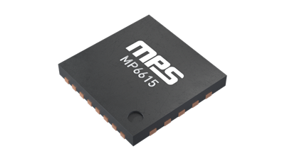
Figure 2: 3D Image of the MP6615
The device’s internal charge pump generates the gate driver voltage and supports 100% duty cycle operation. The device has three different input modes that control the part’s operation, or force it to a high-impedance (Hi-Z) state, which allows the motor to coast. The MP6615 also has an nSLEEP pin for a low-power sleep mode, which is ideal for battery-powered applications.
Protection features include over-voltage protection (OVP), over-current protection (OCP), and thermal shutdown, which prevent the motor or driver from being damaged during abnormal operating conditions. The MP6615 is recommended for medium current industrial applications.
The MPQ6615-AEC1 is the automotive-grade version of the MP6615. It is also an H-bridge motor driver with four N-channel MOSFETs that can deliver a continuous 8A of IOUT. This device is almost identical to the MP6615 and boasts the same features and protections as well as AEC-Q100 Grade 1 qualification. Its applications include vehicle door locks, latch motors, and seat actuators.
Brushless DC (BLDC) Motors: Components and Operation
Although the main difference between a brushed DC motor and BLDC motor is whether the motor has brushes, BLDC motors have additional differences that affect their operation.
BLDC motors have a stator — their stationary component — that contains the windings of the electromagnets. These windings create a magnetic field that can interact with the rotor to produce motion. The rotor is the rotating component that typically contains permanent magnets. These magnets interact with the magnetic field to generate torque and motion. The rotor is supported by bearings, which minimize friction for smooth operation (see Figure 3).
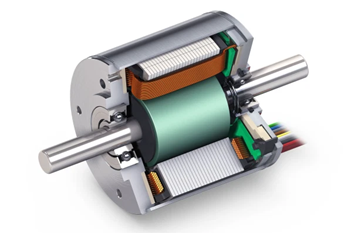
Figure 3: BLDC Motor
BLDC motors often have sensors (e.g. Hall-effect sensors) that detect the rotor’s position and provide feedback to the controller. Sensors are vital to determine which of the stator’s coils need to be energized for motion. BLDC motors require a controller to provide commutation, and to implement speed or torque control.
Brushless DC motors operate following the simplified explanation below:
- When the rotor rotates, the sensors (e.g. Hall-effect sensors) detect the magnet’s positions. This information is then sent to the controller.
- The feedback from the sensors determines which stator coils to energize. As these stators are sequentially energized, the sequence generates a rotating magnetic field.
- The rotor’s magnets align with the magnetic field that is generated by the stator’s coils. This produces torque and makes the motor turn.
The motor maintains direction and speed by energizing different coils.
Brushless DC Motor Drivers
MPS’s integrated BLDC motor driver ICs integrate low on resistance (RDS(ON)) power MOSFETs to enable an incredibly tiny single-chip solution. These BLDC motor drivers can drive brushless DC motors as well as permanent magnet synchronous motors (PMSMs) that can be used in e-bikes, power tools, and automotive applications.
The MP6545 is a three-phase power stage IC designed for BLDC motors and other loads (see Figure 4).
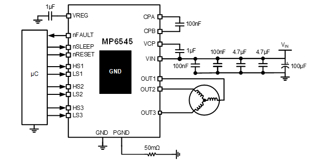
Figure 4: The MP6545 Typical Application Circuit
It provides OCP, OVP, thermal shutdown, and under-voltage lockout (UVLO) with fault indication via the nFAULT pin. It operates across a wide 4.5V to 45V input voltage (VIN) range, and delivers up to 2.5A of IOUT per phase. It is available in two different pages: a tiny QFN-28 (4mmx5mm) package, and a thermally enhanced TSSOP-28EP package. Similar to the MP6615, the MP6545 also has an nSLEEP pin that can force the device into a low-power sleep mode.
The MP6545 is part of a family of similar parts including the MP6545A, MPQ6541-AEC1, and the MPQ6541A-AEC1. These parts also provide current-sensing, robust protections, and low-RDS(ON) MOSFETs.
The MPQ6541-AEC1 is an automotive-grade version of the MP6545, and it offers integrated enable (EN) and pulse-width modulation (PWM) inputs for all three phases. Like the MP6545, the MPQ6541A-AEC1 features HSx and LSx inputs. Both the MPQ6541-AEC1 and MPQ6541A-AEC1 can operate at 100% duty cycle and be used in automotive applications such as LiDAR.
Conclusion
As discussed earlier, DC motors converts electrical energy into mechanical motion that rotates a motor. The article described the functions and components of brushed DC motors and brushless DC (BLDC) motors, while reviewing their important parameters and motor driver ICs that can further optimize the solution.
DC motors are incredibly versatile, efficient, and controllable, which makes them an ideal choice for a number of applications, including the highly specialized medical and automotive industries, as well as being useful for smart home devices. Explore MPS’s website, which features a wide array of brushed DC motor drivers and BLDC motor drivers designed to provide the best possible solution for your end application.
_______________________
Did you find this interesting? Get valuable resources straight to your inbox - sent out once per month!
Technical Forum
 Latest activity 3 days ago
 2 Comments
Latest activity 6 days ago
2 Comments
Latest activity 2 weeks ago
2 Comments
2 Comments
Latest activity 6 days ago
2 Comments
Latest activity 2 weeks ago
2 Comments
Log in to your account
Create New Account