Automotive Electronics Reliability Testing Starts and Ends with the Mission Profile

Get valuable resources straight to your inbox - sent out once per month
We value your privacy
Introduction
Automakers must design vehicles to thrive in a broad spectrum of environments, from snowy tundras to scorching deserts. Unlike most consumer applications, where the expected lifespan can be months, automotive electronics are often expected to last 15 years or more. When specifying a vehicle component, it is common for OEMs and their suppliers to develop an automotive mission profile, which is essentially a summary of all the expected environmental and functional conditions that the component will face during its service life.
Meanwhile, integrated circuits (ICs) used for vehicle components are usually qualified based on the Automotive Electronics Council’s AEC-Q100 standard. Products designed with these specifications in mind — such as MPS’s MPQ8875A-AEC1, a 40W digital buck-boost converter that can deliver 30W in a small 4mmx5mm QFN package — are ideal for ADAS sensor fusion and digital cockpit systems.
This article will help readers better understand how their mission profiles connect to the various electronics reliability tests that are applied to each automotive-grade component during its qualification. This article will explore several frequently asked questions:
- What types of stresses might an electronic component see during its lifetime?
- Who is responsible for determining the reliability capability of chosen ICs in a given design?
- How can I apply the reliability testing “acceleration model” to confirm that a given IC has been tested up to and beyond my mission profile?
In most industries, it is common to estimate the electronics reliability of an application versus its target lifetime. In other words, will the application be able to withstand the overall lifetime stress? To make a reasonable judgment, it is necessary to understand what sorts of stress the application will be subjected to during its field life. Subsequently, this anticipated field life stress must be compared to the stress that all electronic components in the application were originally qualified for. From there, one can determine if the anticipated field life stress would overstress any device in the application, potentially leading to premature failures. This is particularly important for automotive applications, due to the industry’s stringent safety measures.
Mission profiles are designed to mimic a particular type of field stress, as well as its related severity. The most commonly referenced stresses are related to temperature/voltage and thermomechanical stress. Temperature/voltage stress is understood as the main aging effect for the silicon that is used within an IC. This aging effect impacts the material properties such that the IC will see a performance degradation over time. Thermomechanical stress refers to the mechanical forces that occur while a part expands and contracts from temperature variation.
The goal is to understand whether the specified component’s performance can be guaranteed at the end of the application’s targeted life. In other words, will the application’s target life be reached into the wear-out period of the typical semiconductor’s reliability bathtub curve? Due to the inherent life time of semiconductors, the failure rate starts to increase rapidly due to wear. The harder the stress is over time, the earlier the inherent life time is reached, and wear-out failures become more likely (see Figure 1).

Figure 1: Bathtub Curve
Semiconductor manufacturers must qualify a new product before it is released to production and the market. During this qualification process, the ICs are subjected to a number of stress tests to provoke certain fail mechanisms. When considering the aforementioned stresses, there are two particularly useful tests.
The first is the high-temperature operating life (HTOL) test that simulates operating conditions to provoke temperature- and voltage-related fail mechanisms inside a testing chamber (see Figure 2). The second is the temperature cycling (TC) test, which stresses the IC for mechanical fail mechanisms, as the IC is made of different materials that each have different temperature coefficients.
These are just two of the qualification stresses that an IC must pass before it can be released. The whole set of qualification tests for automotive ICs are defined by the AEC-Q100 standards, and many of these tests are also specified in the JEDEC standards. Some applications have even higher electronics reliability requirements, such as trucks and ruggedized vehicle systems, which must be able to handle double the qualification stress for HTOL and TC tests to meet the target Mission Profile requirements. MPS’s MPQ4572-AEC1, a 65V buck converter, is able to meet such stringent reliability requirements while delivering a 2A output.
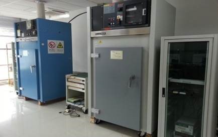
Figure 2: MPS HTOL Chambers
Understanding the Acceleration Factor
The HTOL test is defined by the JEDEC standard, JESD22-A108. A set of 231 units are subjected to 1,000 hours of operation time at 125°C. This test uses the Arrhenius model to determine the acceleration factor (Af), which provides the needed test time (tt) to simulate the equivalent time of real-world operation. Table 1 shows an example with a mission profile that is 12,000 hours of operation at an average junction temperature (TJ) of 87°C. TJ is the temperature of the silicon, and it should be especially considered with ICs that have significant power dissipation, as the ambient temperature (TA) would be much lower than TJ.
Table 1: AEC-Q100, Rev H; Table A7.1 – Basic Calculations for AEC-Q100 Stress Test Conditions and Durations
| Loading | Operation | Thermomechanical |
| Mission Profile Input |
tU = 12,000hr (average operating use time over 15 years) $$A_f = exp \left[\frac{E_a}{K_B} \times \left(\frac{1}{T_u}-\frac{1}{T_t}\right)\right]$$TU = 87°C (average junction temperature in use environment) |
nU = 54,750cls (number of engine on/off cycles over 15 years of use) ∆TU = 76°C (average thermal cycle temperature change in use environment) |
| Stress Test | High-temperature operating life (HTOL) | Temperature cycling (TC) |
| Stress Conditions | Tt = 125°C (junction temperature in test environment) | ∆Tt = 205°C (thermal cycle temperature change in test environment: -55°C to +150°C) |
| Acceleration Model (All Temperatures in degrees K) |
Arrhenius Also applicable for high-temperature storage life (HSL), NVM endurance, data retention bake, and operational life (EDR) |
Coffin Manson $$A_f = \left(\frac{\Delta T_t}{\Delta T_u}\right)^m$$Also applicable for power temperature cycle (PTC) |
| Model Parameters |
Ea = 0.7eV (activation energy; 0.7eV is a typical value, actual values depend on failure mechanism and range from -0.2eV to 1.4eV) kB = 8.61733 x 10⁻⁵eV/K (Boltzmann’s constant) |
m = 4 (Coffin Manson exponent; 4 is used to cracks in hard metal alloys, actual values depend on failure mechanisms and range from 1 for ductile to 9 for brittle materials) |
| Calculated Test Duration |
tt = 1,393hr (test time) $$ t_t = \frac{t_u}{A_f} $$ |
nt = 1,034cls (number of cycles in test) $$n_t=\frac{n_u}{A_f}$$ |
| Q100 Test Duration | 1,000hr | 1,000cls |
For this example, it takes 1,393 hours at 125°C TJ to simulate 12,000 hours at 87°C TJ.
The HTOL qualification asks for 1,000 hours. Using the equations in Table 1, the acceleration factor in the above scenario is calculated to be 8,615, which equals only 8,615 hours at 125°C TJ. With that in mind, the mission profile would exceed the qualification stress by about 40%.
Mission Profile Calculations
Table 2 shows a mission profile, and how it is typically defined.
| Profile | |||
| Active | Passive | ||
| TJ (°C) | Time (h) | TJ (°C) | Time (h) |
| -40 | 45 | -40 | 346 |
| -20 | 45 | 15 | 21168 |
| 40 | 855 | 25 | 42336 |
| 50 | 3150 | 35 | 21168 |
| 60 | 4950 | 40 | 1382 |
| 70 | 9000 | 86400 | |
| 80 | 11250 | ||
| 90 | 6750 | ||
| 100 | 4950 | ||
| 110 | 2700 | ||
| 120 | 1170 | ||
| 125 | 135 | ||
| 45000 | |||
| Total | 131400 | (15-year lifetime) | |
Table 2: Typical Mission Profile
In this example, there are defined active and passive modes, and all of the temperatures are defined as junction temperatures. Thus, active and passive mode do not require differentiation. There are certainly aging effects that are related to current densities when an IC is operating, but these effects are minor when compared to the aging effect of temperature.
Using the Arrhenius equation from Table 1, enter the first data point (-40°C) of the mission profile in Table 2. With a test temperature of 125°C, the acceleration factor (Af) can be calculated with Equation (1):
$$Af=exp\Biggl[\left(\frac{Ea}{kb}\right)\times\left(\frac{1}{273K-40K}-\frac{1}{273K+125K}\right)\Biggl]$$ $$Af=4184927.76$$Using the second equation from Table 1, the acceleration factor, and the second data point (45h) of the mission profile in Table 2, the needed test time (tt) can be calculated with Equation (2):
$$Af=\frac{tu}{tt}$$ $$tt=\frac{tu}{Af}$$ $$tt=\frac{45h}{4184927.76}$$ $$tt=0.000107h$$That means the real-life stress represented by -40°C over 45h would be equal to an HTOL test for just a fraction of an hour at 125°C (see Table 2). In order to calculate the total mission profile stress, all data points of the mission profile must be calculated similarly, and the related equivalent test times must sum to a total of about 5888h. That means that in the real world, the device will receive stresses that are 6 times greater than the stresses it received under testing conditions.
To pass an HTOL test of 1000h means that the device can withstand at least 1000 hours of stress. However, this does not guarantee how much longer past 1000h that the device can withstand the stress. Given that the equivalent stress is 6 times higher than the qualification stress, there is certainly some concern that premature failures may occur.
This is why automotive electronics reliability testing is crucial and devices must be able to withstand high levels of stress. Figure 3 shows Monolithic Power Systems (MPS) devices undergoing an HTOL test.
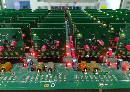
Figure 3: MPS Devices Under HTOL Test Operate Under Load Conditions
In case the mission profile cannot be relaxed (e.g. the associated stress cannot be reduced by bringing down the junction temperature via heatsinking measures), the qualification should be adjusted.
Using this example, do the HTOL qualification at an increased TJ of 150°C. The test time needed to cover the mission profile stress in this scenario is reduced to about 1767h. Note that even higher junction temperatures are not possible, as 150°C is typically the absolute maximum temperature that silicon can be subjected to without being damaged. That being said, the test time for this example would need to be extended to about. 2,000 hours to be on the very safe side. However, even 1,500 hours of qualification test time can provide a fair level of confidence, and can be a reasonable tradeoff relative to testing costs and time.
Mission Profile Definition
Finally, who is actually required to make these calculations, and which party is responsible? For automotive applications, the AEC-Q100 standard provides clarity. In Appendix 7 of Rev. H there is a flowchart that is applicable for the evaluation for existing and qualified components (see Figure 4).

Figure 4: Flowchart A7.2 of AEC-Q100 Rev. H Standard
At first, the mission profile for the electronic control unit (ECU) is determined by the Tier 1, which must be translated into the mission profile that the component would be subjected to. If the component exists and has already been qualified, the basic calculation has already been done by the component manufacturer.
Figure 1 shows the HTOL qualification that represents the basic mission profile outlined earlier in this article. With this data and the Arrhenius model, the Tier 1 can determine whether or not the real-life application mission profile is comparable to the testing conditions. The same is true for mission profiles that refer to parameters other than temperature and voltage stress.
Conclusion
Applications are being designed for increasing reliability requirements under multiple stress conditions. This is predominantly driven by the automotive industry and industrial application requirements. Mission profiles are receiving increased attention, and are required to match the target application’s real-life stressors as closely as possible. IC manufacturers must then design devices that can maintain their specified performance under that anticipated lifetime stress, such as the MPQ8875A-AEC1 and MPQ4572-AEC1 from MPS. It is always a good idea for Tier 1 designers and IC creators to team up early in the process, and evaluate how the application can be designed to best meet the real-life requirements relative to ECU reliability while maximizing cost-effectiveness.
_______________________
Did you find this interesting? Get valuable resources straight to your inbox - sent out once per month!
Technical Forum
 Latest activity a day ago
 3 Comments
Latest activity 5 days ago
2 Comments
Latest activity 3 weeks ago
3 Comments
3 Comments
Latest activity 5 days ago
2 Comments
Latest activity 3 weeks ago
3 Comments
Log in to your account
Create New Account