Analysis and Modeling Method for Electromagnetic Interference (EMI) of Non-Isolated Converters (Part II)

Get valuable resources straight to your inbox - sent out once per month
We value your privacy
Introduction
When not addressed in the earlier design stages, electromagnetic interference (EMI) can make it difficult for parts to meet EMI requirements in the final design stages. Being able to model and analyze EMI helps designers optimize for EMI and predict EMI at the start of their design.
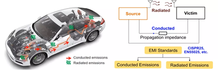
There are two types of EMI: conducted EMI and radiated EMI. Conducted EMI is transmitted via physical contact (to the receiving device through cables or other conductors), while radiated EMI noise does not require physical contact, and is transmitted to the receiving device through open space.
This article will discuss radiated EMI and modeling methods to forecast radiated EMI. To learn more about conducted EMI, see part I of this series.
Related Content
-
ARTICLE
EMI Generation, Propagation, and Suppression in Automotive Electronics (Part II)
Part II will cover radiated EMI modeling strategies based on Thevenin’s Theorem, as well as ground impedance reduction techniques
-
WEBINAR

On-Demand EMC Workshop: EMI Troubleshooting and Debugging
Discover the fundamentals of practical EMI/EMC design and troubleshooting of electronic circuits, using state-of-the-art scopes to analyze your signals in both the time and frequency domains
-
VIDEO

Mythbusting EMC Techniques in Power Converters
Proven ways to improve EMC in your power converter design
-
ARTICLE
EMI Generation, Propagation, and Suppression in Automotive Electronics (Part I)
This article provides modeling and suppression methods to reduce EMI in non-isolated converters, such as buck, boost, and buck-boost converters
Radiated EMI
The traditional methods for determining radiated EMI include using the electromagnetic field theory for derivation and analysis. However, for engineering applications and modeling, deriving the radiated EMI with complicated formulas makes it difficult to fully understand EMI. In addition, it does not explain how to mitigate EMI problems. Instead, it is more useful to create a circuit model for a physical representation of radiated EMI.
Figure 1 shows that the majority of radiated EMI radiates through the dipole sub-antenna. This sub-antenna is comprised of input lines and output lines, and its driving source is the converter’s common-mode noise source.

Figure 1: The Mechanism and Model of Radiated EMI
Using Thevenin’s theorem, the converter can be considered equivalent to a single voltage source with a series impedance. In particular, the antenna uses three impedances that represent its own loss, radiated energy, and stored near-field energy.
For converters, a smaller source results in less radiated energy.
Figure 2 shows that when a non-isolated converter is under ideal conditions (denoted as the top circuit), there is no impedance between the input and output ground. Therefore, there is no voltage variation between the input and output grounds, so the equivalent voltage source (VCM) is zero. This means that there is no radiated EMI noise. However, in a real scenario (denoted as the bottom circuit), due to the inductance generated by the PCB traces between the grounds, a voltage drop occurs between the input terminal (P1) and the output terminal (P3), expressed as ZGND1 and ZGND2. This generates radiated EMI.
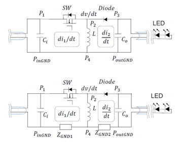
Figure 2: Ideal Circuit Model vs. Actual Buck-Boost Converter
To analyze how radiated EMI generates in a circuit, an equivalent model of the buck-boost converter must be created using the substitution theorem. First, the switch (SW) and the diode are substituted for an equivalent voltage source (VSW) and current source (ID), and their effects are analyzed separately using the superposition theorem.
Figure 3 shows how the VSW voltage source generates radiated noise.
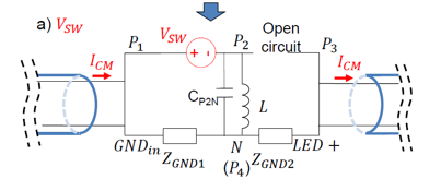
Figure 3: Voltage Source Generates Radiated EMI
Figure 4 shows how the current source (ID) generates radiated noise.
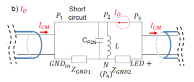
Figure 4: Current Source Generates Radiated EMI
According to the model, it is possible to obtain the transfer function of each source as it relates to the converter’s equivalent source:
- The voltage source and current source can be measured with an oscilloscope.
- Each impedance in the model can be measured with an impedance analyzer.
- The equivalent source can be predicted by calculation.
Figure 5 shows that the predicted values using equivalent sources are close to the actual measured values in the circuit, which signifies that the model is accurate.
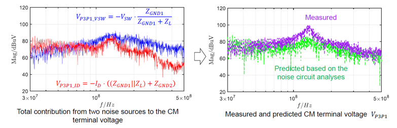
Figure 5: Predicted vs. Actual Buck-Boost Converter Equivalent Source
On the other hand, consider the antenna. Since the length of the wire harness is often determined during testing, the antenna gain can be measured according to the length and arrangement of the wire harness during the EMI test under a certain standard.
By combining the converter’s equivalent source and equivalent impedance, we can predict the actual radiated EMI noise. Figure 6 shows the forecasting process and method. This process begins by determining the initial switching noise and the transfer gain. It is followed by obtaining the CM terminal voltage, the antenna’s transfer gain, and the source and antenna impedance. Then the EMI noise can be accurately predicted.
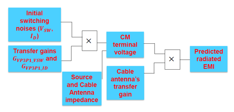
Figure 6: Forecasting Method
Figure 7 shows the comparison between the forecasted results and the actual results. This waveform shows that the two results are similar, which means the forecasting process is a valid way to predict radiated noise.
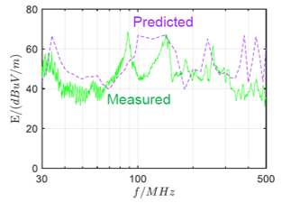
Figure 7: Comparing Predicted Radiated Noise and Actual Radiated Noise
Conclusion
This article discussed the modeling method of conducted and radiated EMI of non-isolated converters using buck converters and buck-boost converters. Part I of this series introduced conducted EMI as well as passive components that can contribute to EMI.
MPS offers a number of non-isolated switching converters and controllers as well as isolated converters to meet your application needs. For automotive applications, MPS’s automotive-grade buck-boost converters and buck converters were designed to meet stringent EMI requirements, in addition to EMC testing laboratories.
_______________________
Did you find this interesting? Get valuable resources straight to your inbox - sent out once per month!
Technical Forum
 Latest activity a day ago
 4 Comments
Latest activity a day ago
2 Comments
Latest activity 3 days ago
2 Comments
4 Comments
Latest activity a day ago
2 Comments
Latest activity 3 days ago
2 Comments
Log in to your account
Create New Account