A Novel Fuel Gauge Solution for High-Voltage Battery Packs

Get valuable resources straight to your inbox - sent out once per month
We value your privacy
Introduction
The increasing adoption of lithium-ion batteries is boosting growth in e-mobility, medical, and robotics markets. Moreover, current application requirements are driving the adoption of larger battery packs with an extended range, longer life, and superior power capabilities.
To guarantee excellent performance, it is vital to address the challenge of estimating a battery’s internal state in battery-based applications. This task is accomplished by the fuel gauge. Fuel gauges accurately estimate the battery’s internal states while providing key information about the battery, such as state-of-charge (SOC), state-of-health (SOH), and power limits. However, developing such complex algorithms requires an in-depth chemical understanding of Li-ion cells, expertise on nonlinear state estimation techniques and control theory, as well as significant resources and time.
This article introduces a novel, highly adaptable fuel gauge for high-voltage battery packs that enables a drastic time-to-market reduction while retaining high estimation accuracy. This article focuses on four key areas: advanced algorithm design, simple system integration, effortless fuel gauge configuration, and quick virtual validation.
Advanced Fuel Gauge Algorithm Design
Fuel gauges use measurable quantities such as current, voltage, and temperature to infer the battery’s internal states. Current-based estimation methods, such as Coulomb counting, monitor the charge going in and out of the battery, whereas voltage-based estimation methods rely on voltage look-up tables. These methods may provide poor estimates when used alone.
The alternative is to use model-based state estimation methods, which combine current-only and voltage-only methods. However, model-based methods rely on a cell mathematical model that captures the cell’s most important dynamics, such as open-circuit and diffusion voltages. Since these dynamics are heavily influenced by internal and environmental factors, their extraction depends on defined characterization tests across the complete cell operating range.
As an example, we’ll look at MPS’s MPF4279x series, a new fuel gauge family that uses an advanced model-based state estimation method to provide high-accuracy battery information, such as pack state-of-charge, remaining charge time, runtime, state-of-health, and power limits.
Table 1 shows an example of the battery pack’s state-of-charge performance under different operating conditions using the MPF42790. The metrics in Table 1 correspond to the state-of-charge root-mean-square error (and maximum state-of-charge error).
Table 1: MPF42790 State-of-Charge Performance
|
Test Case |
15ºC |
25ºC |
35ºC |
|
0.5C charge |
0.80% (1.79%) |
0.87% (1.78%) |
0.98% (1.60%) |
|
1C charge |
0.50% (1.22%) |
0.74% (1.72%) |
0.60% (1.31%) |
|
0.5C discharge |
0.41% (0.88%) |
0.39% (1.12%) |
0.35% (1.39%) |
|
1C discharge |
0.68% (1.38%) |
0.66% (1.26%) |
0.40% (1.05%) |
|
2C discharge |
0.75% (1.99%) |
0.99% (1.61%) |
0.52% (1.71%) |
|
e-bike profile |
1.02% (2.49%) |
1.25% (2.58%) |
0.80% (2.07%) |
Figure 1 shows an example of the MPF42790 pack’s state-of-charge estimation performance, achieving 0.64% state-of-charge root-mean-square error and 1.46% maximum state-of-charge error. The test consists of a complete 1C constant-current and constant-voltage charge, which terminates when the charge current drops to 0.1C, followed by a 1C constant-current discharge on a multi-cell battery pack at 15°C (ambient temperature).
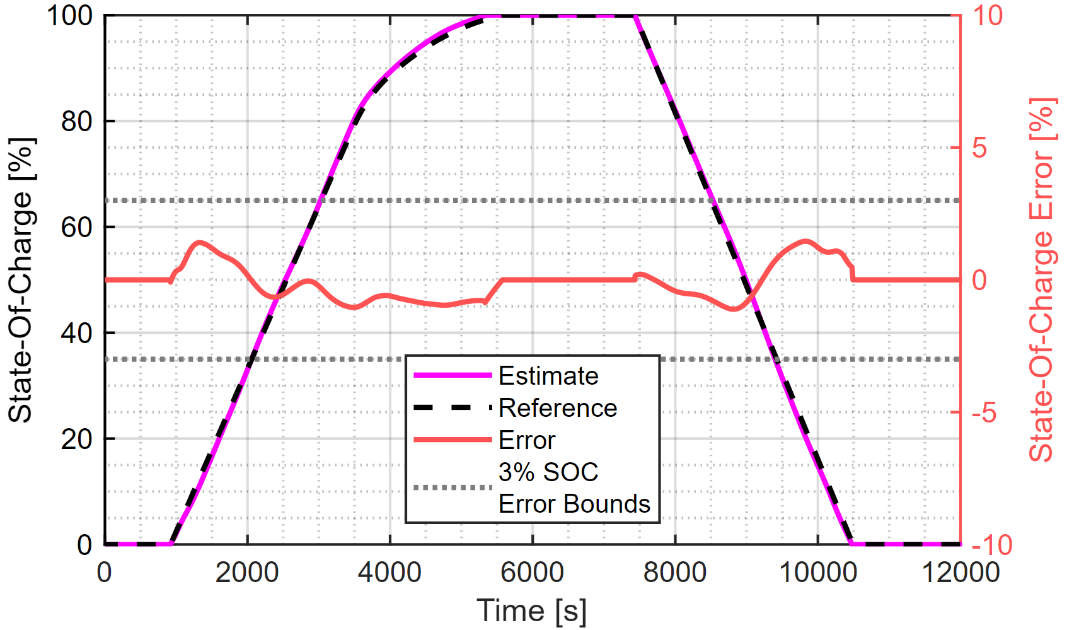
Figure 1: The MPF42790’s Performance for a Complete 1C Charge/Discharge Cycle
MPS’s fuel gauge algorithm relies on high-fidelity electrical cell models generated from a proprietary characterization sequence, proprietary analysis, and optimization tools. This system allows users to easily load any one of these models into the fuel gauge (see Figure 2).
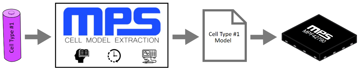
Figure 2: Cell Mathematical Model Generation
Simple Fuel Gauge System Integration
Fuel gauges must provide accurate battery state estimates in real time. Because the fuel gauge relies on periodic cell parameter measurements (e.g., voltage, current, and temperature), the accuracy and reliability of a fuel gauge is limited to the accuracy and reliability of the measurements.
For example, the distribution of cells within the battery pack leads to a temperature gradient due to non-uniform thermal dissipation (see Figure 3). Therefore, a fuel gauge must enable reading multiple temperature sensors to obtain a highly accurate cell-level thermal reading. Otherwise, the state estimation might be less accurate, regardless of the cell model accuracy.
This novel architecture approach receives high-resolution, calibrated measurement data from the analog front end (AFE). This architecture is compatible with any AFE on the market, and is simple to integrate into new or existing electronic designs (see Figure 3). Additionally, users benefit from unprecedented visibility of the cell stack’s internal voltage, which provides key insight into the individual operation of each cell and its influence on the battery pack dynamics.
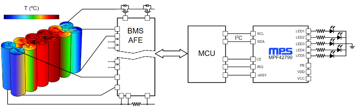
Figure 3: Battery Management System (BMS) Fuel Gauge Architecture
As battery cells become unbalanced or operate at different temperatures, the chemical impedance of each cell diverges, shortening the battery’s runtime and range. The battery pack’s usable state-of-charge is limited by the weakest cell, so monitoring the individual cells’ voltage allows the fuel gauge to deliver a more accurate estimate of the pack’s state-of-charge in real time.
The fuel gauge can accurately estimate the actual state of every cell (or group of parallel cells) in the stack while estimating the battery full and empty conditions (i.e., when the pack is at a 100% or 0% state-of-charge, respectively). These fuel gauge solutions provide full and empty points that reflect both application-specific limits on the battery pack voltage and industry standards, such as IEC62133, that mandate safe operating voltages.
Effortless Fuel Gauge Configuration
The fuel gauge’s operation depends on a mathematical model of the lithium-ion cell. Because battery systems are naturally complex, multiple parameters must be adjusted to optimize the fuel gauge.
Even if the cell model is provided, battery-based systems still require a lengthy validation process due to the number of parameters. A longer validation process can cause severe setbacks in the testing schedule, which increases costs and time-to-market. To address this issue, fuel gauges can be simplified by using a graphic user interface (GUI) for users to manually fine-tune the fuel gauge.
For example, MPS’s fuel gauge GUI establishes two specific configuration modes: basic and advanced configuration mode. Basic mode allows users to configure the primary parameters that make the fuel gauge operational (see Figure 4), while advanced (also called expert) mode allows users to configure additional settings for their design. Additionally, MPS’s fuel gauge can self-adjust parameters that have a strong influence on the pack’s state-of-charge estimate in real time.
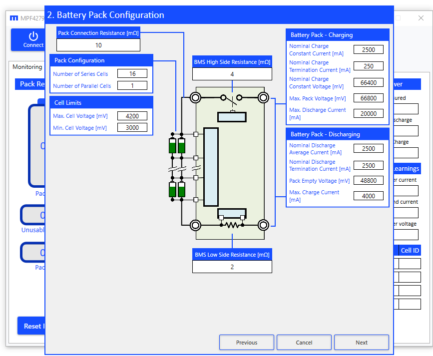
Figure 4: MPS’s Fuel Gauge GUI
Quick Virtual Validation
Multiple tests must be carried out to validate a fuel gauge’s operation. These tests are designed to imitate how the battery is typically used in the final application, how the battery ages, and how it acts under certain conditions, such as extreme temperatures or high currents.
However, if the fuel gauge settings are changed, many validation tests must be repeated to ensure optimal performance, which demands resources and time. Ideally, a single set of tests could determine the optimal fuel gauge configurations while simultaneously reducing safety risks and time-to-market.
The MPF42790 includes this novel feature, which enables quick resimulation of any battery pack test under different configuration parameters (see Figure 5). First, the test data is recorded and exported to a common file format using the GUI. Next, the exported test data is loaded into the GUI and resimulated using the updated fuel gauge settings.
This feature also enables quicker, customized support, since recorded test data and fuel gauge configuration files can be easily shared with MPS to replicate and analyze results.
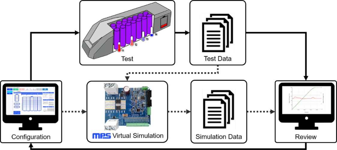
Figure 5: Fuel Gauge Validation Diagram, Including Virtual Simulation (Dashed Lines)
Conclusion
As battery-based solutions become increasingly popular, several challenges must be addressed to ensure safe operation and user satisfaction. One challenge is how to accurately estimate the battery’s internal states across all of its stacked lithium cells, since these cells provide key information about the battery operation.
Fuel gauges, such as the MPF42790 from MPS, must provide optimal performance in addition to adaptable designs, simple GUIs, and virtual testing capabilities. These highly adaptable devices enable designers to resimulate previously recorded tests, which significantly speeds up configuration, testing, and validation.
_______________________
Did you find this interesting? Get valuable resources straight to your inbox - sent out once per month!
Technical Forum
 Latest activity 11 hours ago
 1 Comment
Latest activity a day ago
1 Comment
Latest activity 4 days ago
1 Comment
1 Comment
Latest activity a day ago
1 Comment
Latest activity 4 days ago
1 Comment
Log in to your account
Create New Account