


Fundamentals of Multilevel Converter Topologies
Advanced power electronic devices known as multilevel converters are made to take many levels of DC input voltage and produce a desired output voltage waveform. Because these converters can provide waveforms with better harmonic content, less electromagnetic interference (EMI), and less voltage stress on power devices, they have grown in significance in high-power and high-voltage applications. The fundamental principle behind multilevel converters is to combine multiple DC voltage levels to create an output voltage waveform that resembles a staircase and more closely resembles a sinusoidal waveform. This method increases the efficiency and reliability of power electronic systems in addition to improving power quality.
Overview of Multilevel Converter Topologies
There are various topologies into which multilevel converters can be classified, each with its own advantages, structure, and operating principles. The topologies of multilevel converters that are most frequently used include:
- Diode-Clamped Multilevel Converter (DCMC)
- Flying Capacitor Multilevel Converter (FCMC)
- Cascaded H-Bridge Multilevel Converter (CHBMC)
Diode-Clamped Multilevel Converter (DCMC)
Structure and Operation: One of the most popular multilevel converter topologies is the Diode-Clamped Multilevel Converter, also referred to as the Neutral-Point Clamped (NPC) converter. A series of capacitors are employed in this topology to divide the DC bus voltage into several levels, and clamping diodes are used to link each level to the proper phase output. By limiting the switching devices' exposure to a small portion of the overall DC bus voltage, the diodes efficiently "clamp" the voltage levels, lowering the voltage stress on each device.
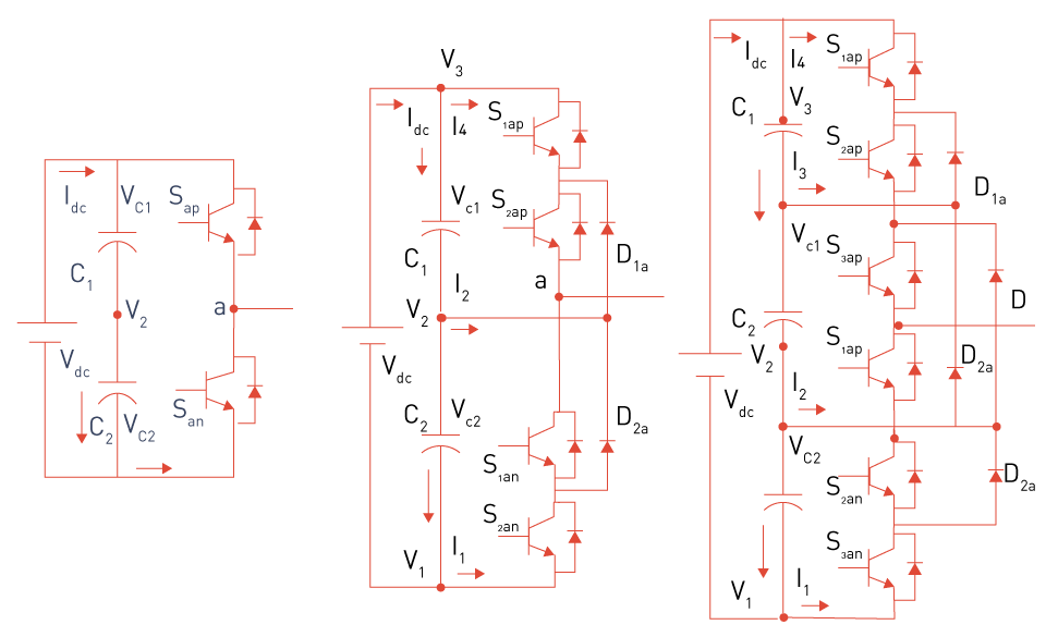
Figure 11: Two-level, three-level and four-level inverters
Advantages:
- Reduced voltage stress on power devices enables the use of lower-rated components.
- Enhanced harmonic performance in contrast to converters with two levels.
- An excellent fit for high-power applications like HVDC systems and medium-voltage drives.
Challenges:
- As the number of levels rises, the number of clamping diodes also rises, increasing complexity and potentially causing issues with reliability.
- For higher-level converters to function properly, the capacitor voltages must be balanced.
Flying Capacitor Multilevel Converter (FCMC)
Structure and Operation: Instead of using diodes to achieve multiple voltage levels, the Flying Capacitor Multilevel Converter uses capacitors. The voltage levels in this topology are generated by carefully charging and discharging a series of capacitors that are connected in parallel with the power switches. The intermediate voltage levels are produced by connecting capacitors between each pair of switches that make up each phase leg of the converter.
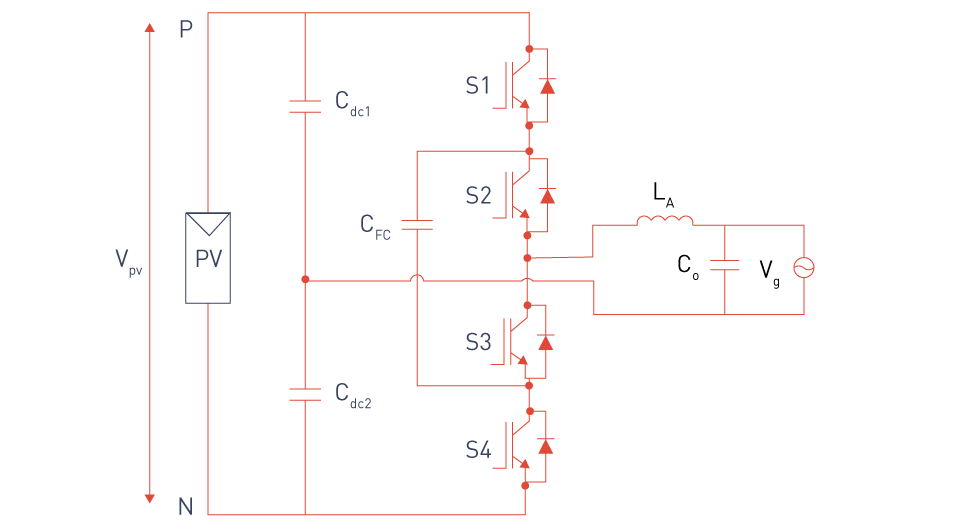
Figure 12: Half-bridge three-level PV inverter
Advantages:
- Provides additional switching options that can be utilized to balance capacitor voltages and improve waveform quality.
- Enhanced fault tolerance as a result of the flying capacitors' redundancy.
- It is relatively easy to extend to higher voltage levels.
Challenges:
- Requires a large number of capacitors, increasing the converter's size, cost, and complexity.
- It can be complex to manage capacitor charging and discharging to keep voltage balanced.
- Compared to other topologies, the control scheme is more complex.
Cascaded H-Bridge Multilevel Converter (CHBMC)
Structure and Operation: The Cascaded H-Bridge Multilevel Converter consists of numerous H-bridge inverter units connected in series on the AC side. A different DC source, such as a battery, solar panel, or other energy storage device, powers each H-bridge unit independently. Because the CHB topology is modular, the converter can produce a highly granular output voltage waveform with numerous levels by cascading multiple H-bridge units.
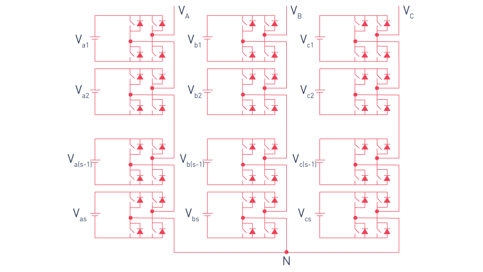
Figure 13: Three-phase wye configuration CHBMC
Advantages:
- Easy scalability to higher voltage levels and powers is made possible by modular design.
- Excellent output waveform that requires minimal filtering.
- Each H-bridge unit functions separately, which provides fault tolerance and redundancy.
Challenges:
- Need several separate DC sources, which can make the design of the power supply more complicated.
- Higher costs and potential reliability issues result from the number of components increasing linearly with the number of levels.
- Coordinating the operation of multiple H-bridge units requires complex control strategies.
Applications of Multilevel Converter Topologies
The exceptional performance of multilevel converters in terms of efficiency, voltage management, and harmonic reduction makes them popular in a variety of high-power and high-voltage applications. Common uses include the following:
Medium-Voltage Drives: Multilevel converters minimize harmonic distortion while providing efficient control of large motors in medium-voltage motor drives used in industrial applications including compressors, fans, and pumps.
High-Voltage Direct Current (HVDC) Transmission: To efficiently convert and transmit large amounts of electricity across long distances with low losses, multilevel converters are used in HVDC transmission systems.
Renewable Energy Systems: Multilevel converters are used in photovoltaic (PV) and wind power systems to interconnect the DC output of solar panels or wind turbines to the AC grid, guaranteeing effective energy conversion and high-quality power delivery.
Flexible AC Transmission Systems (FACTS): To control voltage, power flow, and other parameters and improve the stability and reliability of power grids, multilevel converters are essential components of FACTS devices such unified power flow controllers (UPFCs) and static compensators (STATCOMs).


Pulse Width Modulation (PWM) Techniques for Multilevel Converters
A crucial method in multilevel converters, Pulse Width Modulation (PWM) modifies the widths of the pulses in a switching signal to regulate the output voltage and current. PWM techniques are used in multilevel converters to minimize switching losses and harmonic distortion while generating a high-quality output waveform that approximately matches a sinusoidal signal. PWM techniques for multilevel converters are more complex than those for traditional two-level converters because of the higher number of voltage levels in these converters. The primary PWM methods utilized in multilevel converters are explored in this section, along with their benefits, applications, and underlying principles.
Overview of PWM Techniques in Multilevel Converters
Generating a staircase-like output waveform that closely mimics a sine wave is the main objective of PWM in multilevel converters. PWM techniques can modify the output waveform's amplitude, frequency, and phase to satisfy the required performance criteria by regulating the timing of the switching devices. Multilevel converters' higher level count enables more precise control over the output waveform, which lowers total harmonic distortion (THD) and improves power quality.
The following are some of the most popular PWM techniques for multilevel converters:
- Sinusoidal PWM (SPWM)
- Space Vector Modulation (SVM)
- Selective Harmonic Elimination PWM (SHE-PWM)
- Level-Shifted PWM (LS-PWM)
- Phase-Shifted PWM (PS-PWM)
Sinusoidal PWM (SPWM)
One of the most popular modulation methods in power electronics is sinusoidal PWM (SPWM). Multiple triangular carrier waves that correspond to each voltage level are compared with a sinusoidal reference waveform, or the intended output voltage, in multilevel converters using SPWM. The places at which the sinusoidal reference meets the carrier waves determine the switching instants of the converter's power devices.
The output voltage of a three-level converter is determined by comparing the sinusoidal reference with two triangular carriers. A staircase waveform that resembles the sinusoidal reference is produced when the switching devices are activated in response to the comparison. A high switching frequency and precise control over the output voltage are the results of the triangular carriers' frequency, which is often significantly higher than the reference waveform's frequency.
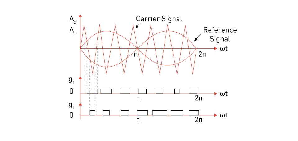
Figure 14: Gate Signal Generation in Sinusoidal PWM
Advantages:
- Widely understood and easy to implement.
- Efficient in minimizing lower-order harmonics.
- Ideal for uses where moderate to high switching frequencies are required.
Challenges:
- May lead to increased switching losses because of the carrier waves' high frequency.
- In certain applications, especially high-power systems, THD reduction might not be the best option.
Space Vector Modulation (SVM)
An advanced PWM technique called Space Vector Modulation (SVM) uses vectors in a two-dimensional plane to represent the inverter's output voltages. The main idea is to approximate the reference voltage vector by switching between the multilevel converter's available voltage vectors in such a way that the error is minimized across the sampling interval.
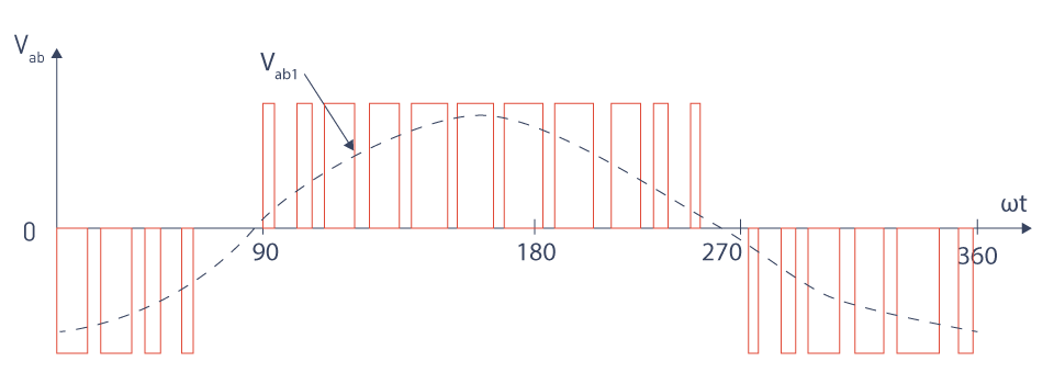
Figure 15: Example output voltage in SVM
The space vector plane in SVM for a three-level converter is separated into multiple sectors, each of which is linked to a different switching state. To provide the desired output, the converter alternates between the voltage levels by identifying the sector that contains the reference vector. SVM is very good at lowering switching losses and making use of the available DC bus voltage.
Advantages:
- When compared to SPWM, it uses the DC bus voltage more efficiently.
- Reduces switching losses by limiting the number of switch transitions.
- It produces lower THD in the output waveform, making it appropriate for high-performance applications.
Challenges:
- More difficult to implement, requiring a thorough understanding of space vector theory.
- Computationally intensive, especially for converters with a large number of levels.
Selective Harmonic Elimination PWM (SHE-PWM)
Selective Harmonic Elimination PWM (SHE-PWM) is a technique designed especially to remove particular harmonics from the output waveform. In order to minimize or eliminate certain harmonics while maintaining the required fundamental voltage, a set of non-linear equations that determine the switching angles must be solved.
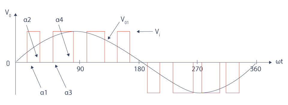
Figure 16: Typical Output Waveform for 3rd, 5th, and 7th Harmonic Elimination with SHE Modulation
To remove the selected harmonics, the switching angles in SHE-PWM for a multilevel converter are precalculated. The timing of the switching devices is then managed by these angles. The technique entails resolving a set of transcendental equations, which can be computationally demanding, particularly when trying to eliminate higher-order harmonics or for converters with more levels.
Advantages:
- Capable of removing specific harmonics to achieve extremely low THD.
- Ideal for applications such as power quality improvement devices, where harmonic performance is crucial.
- Eliminates the need for extra filtering components.
Challenges:
- The non-linear equations can be complex and time-consuming to solve.
- Limited flexibility because the switching angles are fixed and must be adjusted if the operating conditions change.
Level-Shifted PWM (LS-PWM)
The technique known as Level-Shifted PWM (LS-PWM) uses multiple carrier signals, each of which corresponds to a distinct voltage level in the converter. To determine the switching instants, these carriers are vertically moved relative to one another, and each carrier is compared to reference waveform.
Three triangular carriers, each offset by a certain voltage level, are compared to the reference waveform in an LS-PWM scheme for a three-level converter. A stepped output waveform with fewer harmonics is produced as a result of a modulation process in which the switches are turned on in response to the comparison.
Advantages:
- Simple to implement and comprehend, similar to SPWM.
- Offers excellent harmonic performance, particularly when the number of levels is high.
- Can be effortlessly expanded to include converters with more levels.
Challenges:
- Switching losses are higher as the number of switching events increases.
- Additional filtering may be required to obtain very low THD in high-power applications.
Phase-Shifted PWM (PS-PWM)
With Phase-Shifted PWM (PS-PWM), the carrier signals are not level-shifted but rather phase-shifted in respect to one another. Because each H-bridge module has its own phase-shifted carrier, this method works especially well in cascaded H-bridge multilevel converters.
PS-PWM distributes the switching events over the entire switching period by phase-shifting the carriers for each H-bridge module by an equal amount. This lower switching losses and improves thermal performance by lowering the total switching frequency that each power device experiences.
Advantages:
- Distributes switching events throughout time to minimize switching losses.
- Offers a reduced THD with high-quality output waveform.
- Very efficient in modular multilevel converters and cascaded H-bridge converters.
Challenges:
- Phase shifts between carriers must be precisely synchronized.
- Control system is more complex than in other PWM techniques.
Applications of Multilevel Converters in Power Systems
Multilevel converters have become an essential component of modern power systems, particularly in applications needing high voltage, high power, and improved power quality. Their ability to provide high-quality output waveforms with low harmonic distortion and low voltage stress on switching devices makes them suitable for a wide range of power system applications. This section delves into the key uses of multilevel converters in power systems, focusing on high-voltage direct current (HVDC) transmission, renewable energy integration, medium-voltage drives, and flexible AC transmission systems (FACTS).
Renewable Energy Integration
Photovoltaic (PV) Power Plants: Photovoltaic (PV) power plants frequently use multilevel converters to convert the DC output from solar panels into AC power that can be connected to the grid. The cascaded H-bridge multilevel converter (CHBMC) is especially advantageous because solar arrays are modular. An individual solar panel or string can power each H-bridge, enabling scalable, effective power conversion with low harmonic distortion. The overall efficiency of the PV power plant is increased by multilevel converters' capacity to function at higher voltage levels with reduced switching losses.
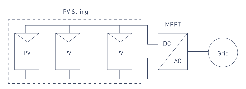
Figure 17: PV string

Figure 18: Three-phase multilevel PV inverter
Wind Energy Systems: Multilevel converters are used in the power electronics interface between the grid and wind turbine generators in wind energy systems. These converters control the wind turbine's fluctuating frequency and voltage output, guaranteeing steady and high-quality electricity delivery to the grid. Multilevel converters are ideally suited for this application due to their higher harmonic performance and ability to handle varying voltage levels, especially in offshore wind farms where long-distance and high voltage transmission is necessary.
High-Voltage Direct Current (HVDC) Transmission
Overview of HVDC Systems: The ability to transmit large power over long distances with minimal losses makes HVDC transmission an essential technology. It is especially helpful for connecting asynchronous power grids and for supplying load centers with electricity from distant renewable energy sources. Multilevel converters, also known as voltage source converters (VSCs), are utilized in HVDC systems because of their great efficiency in converting AC to DC (rectification) and DC to AC (inversion).
Role of Multilevel Converters: The preferred choice for VSC-HVDC systems is a multilevel converter, particularly a modular multilevel converter (MMC). Long-distance power transmission requires exceptional scalability to very high voltage levels, which the MMC topology offers. MMCs perform better when it comes to lowering switching losses, enhancing power quality, and lowering harmonic distortion. Additionally, they offer inherent redundancy, which improves HVDC systems' reliability.
Medium-Voltage Drives
Industrial Applications: Medium-voltage drives are used in industrial applications to regulate the speed and torque of large motors in pumps, fans, compressors, and conveyors. These motors typically run at voltages ranging from 1 kV to 13.8 kV and require complex control systems to improve performance and efficiency. Multilevel converters, specifically the diode-clamped (DCMC) and cascaded H-bridge (CHB) topologies, are widely employed in medium-voltage drives.
Benefits of Multilevel Converters: The ability of multilevel converters to generate a high-quality output waveform with less harmonic distortion is their primary advantage when used in medium-voltage drives. By lowering thermal and electrical stresses, this increases motor efficiency, decreases the need for large, costly filtering components, and extends the motor's lifespan. Multilevel converters are also highly reliable for crucial industrial applications due to their modular design, which makes scaling and redundancy easier.
Energy Efficiency: Through the optimization of power factor and the reduction of reactive power usage in industrial processes, multilevel converters help to promote energy efficiency. Because multilayer converters have a reduced environmental footprint and lower operating costs, they are a desirable option for energy-conscious enterprises.
Flexible AC Transmission Systems (FACTS)
Overview of FACTS: Advanced power electronics devices called Flexible AC Transmission Systems (FACTS) are utilized to improve power grid efficiency, stability, and controllability. Power quality issues such as reactive power imbalance and harmonics are mitigated by FACTS devices, which also help control the flow of electricity and maintain voltage levels.
Role of Multilevel Converters in FACTS: A variety of FACTS device types, such as Unified Power Flow Controllers (UPFCs) and Static Synchronous Compensators (STATCOMs), rely on multilevel converters for operation. Multilevel converters in these situations give the FACTS device exact control over the voltage and current waveforms, allowing it to work as intended.
STATCOMs: A variable AC voltage that can be injected into the grid to regulate reactive power and stabilize voltage levels is produced by multilevel converters in a STATCOM. A multilevel converter's high-quality output waveform minimizes the need for extra filtering and enhances the STATCOM's overall performance.
UPFCs: Multilevel converters are employed in a UPFC to regulate the transmission line's active and reactive power flows. By enabling dynamic control of electricity flow, this feature raises the grid's stability and efficiency.
Advantages: Among the many advantages of using multilayer converters in FACTS devices are lower switching losses, lower harmonic distortion, and enhanced reliability. These advantages are essential for guaranteeing that FACTS devices can function well under a variety of grid conditions, including fault and normal operation.
Control Challenges and Solutions
Multilevel converters, while providing various benefits such as increased power quality, decreased harmonic distortion, and efficient high-voltage power conversion, pose a unique set of control challenges. These difficulties originate from the increased complexity of the converter topology, the requirement for precise modulation techniques, and the need to handle the interactions between multiple voltage levels and switching devices. For multilevel converters to operate reliably and efficiently in a variety of applications, such as industrial motor drives, HVDC transmission, and renewable energy systems, these control issues must be resolved. The main control issues with multilevel converters are examined in this section, along with possible ways to address them.
Voltage Balancing
Challenge: Maintaining the balance of capacitor voltages is one of the biggest challenges in multilevel converters, especially in diode-clamped and flying capacitor topologies. Because the DC bus voltage in these topologies is distributed among multiple capacitors, any imbalance may result in uneven voltage levels, which could cause system instability, higher stress on power devices, and decreased efficiency. Higher-level converters, which have more capacitors and more complicated voltage balancing, make this issue worse.
Solution: A number of strategies can be used to solve voltage balance challenges:
- Active Voltage Balancing: This approach redistributes the charge among the capacitors by dynamically altering the converter's duty cycles or switching sequences. Capacitor voltages can be monitored and real-time adjustments applied to maintain balance using control algorithms like model predictive control (MPC) or feedback-based control.
- Redundant Switching States: The controller can actively balance the capacitor voltages without affecting the overall output waveform by choosing the right redundant states, which are often found in converters with more levels, where many switching states might yield the same output voltage.
- Flying Capacitor Design: In flying capacitor topologies, balanced operation requires careful control parameter selection and proper design, and appropriate capacitor values and switching methods can assist guarantee natural voltage balancing.
Harmonic Distortion and Filtering
Challenge: Despite the fact that multilevel converters are made to generate output waveforms with less harmonic content than traditional two-level converters, controlling and reducing harmonic distortion is still a challenge. Increased losses, issues with power quality, and interference with other grid-connected equipment can all result from harmonic distortion. Harmonic control is especially difficult because of the converter topology's complexity and the requirement for precise synchronization of multiple switches.
Solution: There are a number of solutions to reduce harmonic distortion in multilevel converters, as follows:
- Advanced PWM Techniques: Harmonic distortion can be considerably decreased by employing advanced pulse width modulation (PWM) techniques like Space Vector Modulation (SVM) or Selective Harmonic Elimination (SHE-PWM). By using these methods, switching instants can be precisely controlled to improve the harmonic spectrum overall or minimize particular harmonics.
- Active Filtering: To further minimize harmonics, active filtering techniques can be employed in addition to passive filters. Active filters enhance the system's overall power quality by using power electronics to introduce compensatory currents that eliminate undesirable harmonics.
- Optimized Converter Design: Harmonics can be reduced at the source by carefully designing the converter topology, which includes choosing the right switching devices, capacitors, and inductors. Modular converter designs, such as the Cascaded H-Bridge (CHB) topology, can also improve harmonic performance by enabling finer control over the output waveform.
Switching Losses and Efficiency
Challenge: The high number of switching devices needed for multilevel converters adds to the total switching losses. These losses can result in decreased efficiency and greater thermal stress on the converter's components, especially in high-power applications. A challenge lies in reducing switching losses without sacrificing reliable operation and high-quality output waveforms.
Solution: Several strategies can be used to lower switching losses and boost efficiency:
- Reduced Switching Frequency: Reducing the switching frequency is one of the most effective strategies to minimize switching losses. Advanced modulation techniques, such Phase-Shifted PWM (PS-PWM), which distribute the switching events among several devices and lower the effective switching frequency that each device perceives, can be used to accomplish this.
- Soft-Switching Techniques: To reduce switching losses, soft-switching methods like Zero-Voltage Switching (ZVS) or Zero-Current Switching (ZCS) can be employed. These methods minimize the energy dissipated during each switching event by guaranteeing that the switching transitions take place when there is zero voltage or zero current.
- Efficient Component Selection: Switching losses can be greatly impacted by the selection of switching devices, such as Silicon Carbide (SiC) MOSFETs or Insulated Gate Bipolar Transistors (IGBTs). Devices with lower switching losses and higher efficiency should be chosen based on the application's requirements.
Complexity in Control Algorithms
Challenge: Multilevel converter control is inherently more complex than traditional converter control because of the increased number of switching states, the need for precise synchronization, and the need to manage multiple control objectives at the same time (e.g., voltage balancing, harmonic reduction, and efficiency optimization). One of the biggest challenges is creating control algorithms that can manage this complexity in real-time.
Solution: The following strategies can be used to control the complexity of control algorithms:
- Model Predictive Control (MPC): Multiple control objectives and constraints can be handled simultaneously using MPC, a powerful control strategy. MPC can optimize the control actions at each time step by predicting future system behavior, guaranteeing that the converter runs effectively and within its limits.
- Hierarchical Control Structures: The control tasks in complex systems can be divided into several levels using a hierarchical control structure, where each level handles a specific aspect of the control problem. A high-level controller can manage the overall objectives of the system, for instance, whilst lower-level controllers handle specific converter modules or control loops.
- Digital Signal Processing (DSP) and Field-Programmable Gate Arrays (FPGAs): Complex control algorithms must be implemented in real time, requiring large processing resources. Multilevel converter control systems frequently use DSPs and FPGAs to provide the processing power and adaptability required to execute complex control algorithms.
Fault Tolerance and Reliability
Challenge: Multilevel converters include a lot of components, making fault tolerance and reliability difficult to achieve. Reduced performance, system instability, or even catastrophic failure might result from faults in switching devices, capacitors, or control circuits. Maintaining reliable operation requires the development of control strategies that are able to identify, isolate, and compensate for faults.
Solution: There are various approaches to improve multilevel converters' fault tolerance and reliability:
- Redundancy: In the case of a component failure, redundancy can be incorporated into the converter design by employing extra capacitors or switching devices. This method guarantees that until repairs are possible, the converter can keep operating, albeit with reduced performance.
- Fault Detection and Diagnosis: Advanced algorithms for fault diagnosis and detection can track the health of the converter's components in real time and identify irregularities that can indicate a fault. Corrective measures, such reconfiguring the converter to bypass the faulty component or modifying the control strategy to compensate for the fault, can be taken by the control system once a fault has been identified.
- Modular Design: Modular converter topologies, such as the CHB or MMC, have inherent fault tolerance because each module functions separately. If a defect occurs in one module, the system can continue to function with the remaining modules, minimizing the impact on overall system performance.
Log in to your account
Create New Account