How to Avoid Inductor Saturation in your Power Supply Design

Get valuable resources straight to your inbox - sent out once per month
We value your privacy
An inductor is an important component of a DC/DC power supply. There are many considerations to make when choosing an inductor, such as inductance value, DCR, size, and saturation current. The saturation behavior of the inductor is often misunderstood and can be troublesome. This article will address how inductors become saturated, how saturation affects the circuit, and methods to detect inductor saturation.
Reasons for Inductor Saturation
To understand how an inductor becomes saturated, see Figure 1 and the steps for inductor saturation described below:
- When current is passed through the coil in Figure 1, the coil generates a magnetic field.
- The magnetic core is magnetized by the field, and its internal magnetic domain rotates slowly.
- When the magnetic core is completely magnetized, the direction of the magnetic domains become consistent with the magnetic field. Even if an external magnetic field is added, the core has no rotating magnetic domains. This means the inductor is saturated.

Figure 1: Inductor Saturation Diagram
Figure 2 shows another perspective of inductor saturation, as well as an equation that shows how the system’s flux density (B) and magnetic field strength (H) can affect inductance.
When the magnetic flux density reaches BM, the magnetic flux density no longer increases with the magnetic field strength. This means the inductor is saturated.
Consider the relationship between inductance and permeability (µ). When the inductor is saturated, µ is greatly reduced; therefore the inductance will be greatly reduced and the ability to suppress the current is lost.

Figure 2: Magnetization Curve and Formulas
Tips for Judging Inductor Saturation:
There are two categories to judge inductor saturation in practical applications: theoretical calculations and experimental tests. Figure 3 summarizes these methods.

Figure 3: Methods to Determine Inductor Saturation
Theoretical calculations require calculating the maximum magnetic flux density or the maximum inductor current. On the other hand, experimental tests mainly focus on the inductor current waveform and other preliminary judgment methods. These methods are described in more detail below.
Method 1: Calculating the Magnetic Flux Density
Method 1 is suitable for scenarios where magnetic cores are used to design inductors. For example, the core parameters include the magnetic path length (lE) and the effective area (AE). The type of the magnetic core also determines the corresponding magnetic material grade, and the magnetic material necessitates corresponding regulations on the core loss and saturation magnetic flux density (see Figure 4).

Figure 4: Inductor Parameters and Characteristics
With these materials, we can calculate the maximum magnetic flux density according to the actual design scenario. Figure 5 shows the formulae to calculate the maximum magnetic flux density.

Figure 5: Magnetic Flux Density Formulas
In practice, the calculation can be simplified, and µI can be used instead of µR. When compared to the saturation flux density of the magnetic material, it can be determined whether the designed inductance is at risk of saturation.
Method 2: Calculating the Maximum Inductor Current
This method is suitable for designing circuits by directly using existing inductors. Different circuit topologies have different formulas for inductor current calculation.
Take the MP2145, a switch-mode converter, as an example. The inductor current can be calculated according to the formulae below, and compared the calculation result with the inductor specification value to determine whether the inductor will be saturated (see Figure 6).

Figure 6: Calculating Maximum Inductor Current with the MP2145
Method 3: Determine Whether the Inductor is Saturated by the Inductor Current Waveform
This method is the most common and practical method available for engineers.
Use the MPSmart simulation tool with the MP2145. From the simulation waveform, we know that when the inductor is not saturated, the inductor current is a triangular wave with a certain slope. When the inductor is saturated, the inductor current waveform has significant distortion, which is caused by the decrease in the sense of saturation (see Figure 7).

Figure 7: Inductor Current Waveform for the MP2145
We can observe distortion in the inductor current waveform to determine when it becomes saturated.
Figure 8 shows the measured waveform on the MP2145 evaluation board. There is an obvious distortion after the inductor becomes saturated, which is consistent with the simulation results.

Figure 8: MP2145 Evaluation Board Waveform
Method 4: Measure the Abnormal Temperature Rise of the Inductor and Listen for Audible Sounds
If you do not know a system’s core model, it may be difficult to determine the saturation current of the inductor. Sometimes it is inconvenient to test the inductor current, as it may require partially lifting the inductor off the PCB to measure its current. Another trick is to measure the inductor temperature with a thermal camera. If the temperature significantly exceeds the design expectation, that may indicate that the inductor is saturated (see Figure 9). If you put your ear close to the inductor and find that it is emitting sounds, this may also indicate that it is saturated.
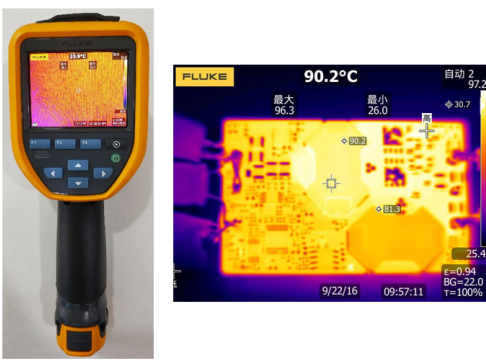
Figure 9: Measuring Inductor Temperature Using a Thermal Camera
When designing power supplies with inductors, it is important to avoid saturating your inductor. This article explained some of the physical behaviors that cause magnetics to saturate, and provided equations to choose the proper inductance value for your circuit, scope pictures of what current waveforms look like when the inductors become saturated, as well as other tricks to observe inductor saturation in your application. To choose an inductor for your next design project, see our new catalog of inductors.
_________________________
Did you find this interesting? Get valuable resources straight to your inbox - sent out once per month!
Technical Forum
 Latest activity 5 years ago
 9 Comments
Latest activity 11 months ago
5 Comments
Latest activity 3 years ago
8 Comments
9 Comments
Latest activity 11 months ago
5 Comments
Latest activity 3 years ago
8 Comments
Log in to your account
Create New Account