How Battery Characteristics Impact Battery Management

Get valuable resources straight to your inbox - sent out once per month
We value your privacy
Introduction
Battery management refers to the critical task of monitoring, protecting, and controlling batteries, particularly with rechargeable battery packs, where many batteries are connected in series or parallel. A battery management system (BMS) consists of a battery monitor, microcontroller (MCU), and fuel gauge. The BMS ensures safe, reliable, and optimal operation by protecting the system and battery, and prolonging the system lifespan (see Figure 1).

Figure 1: Battery Management System
This article will provide a brief overview of some of the key physical and electrical characteristics of battery cells that affect their performance, behavior, limitations, and application uses. Specifically, this article focuses on a few key parameters: battery chemistry, voltage, current, capacity, energy density, and power density (see Figure 2). All of these factors affect the battery management system (BMS) by creating specifications that designers must follow when creating their solution.
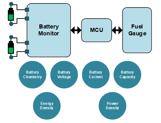
Figure 2: Factors Affecting the BMS
Related Content
-
ARTICLE

Battery Management Systems: How Battery Chemistry Affects Battery Charger IC Selection
This article will discuss the benefits and challenges of four battery chemistries (Li-ion, LFP, Li-polymer, and NiMH) in battery applications under 30V.
-
VIDEO
Battery Monitor and Protector IC for Energy Storage: MP2797/MP2787
Get to know MPS's MP2797 and MP2787 high-accuracy battery monitor and protector ICs for analog front-end (AFE) monitoring and protection for 7-cell to 16-cell series battery packs.
-
ARTICLE
Battery Charger IC Fundamentals
Li-ion battery charger ICs are devices that regulate battery charging current and voltage, and are commonly used for portable devices, such as cellphones, laptops, and tablets.
-
USE CASE
Analog Front-End (AFE) Monitoring and Protection IC Use Case: Lithium Battery E-Bikes
This use case examines the application of the MP2797 in lithium battery e-bikes.
Battery Chemistry
Battery chemistry is important when designing a BMS because each battery type has distinct characteristics that influence how the BMS must monitor and protect the battery pack. Different applications have different requirements for size, power, safety, reliability, lifetime, and cost. This makes specific chemistries better suited for certain applications.
Battery chemistry determines the battery cell voltage in addition to its limits and optimal conditions, such as those regarding voltage, current, temperature, resistance, and capacity. For example, lead acid batteries have a nominal voltage of 2.2V, while Li-ion batteries have a nominal voltage of about 3.7V. In addition, battery chemistry can impact the optimal charging method and battery charger IC selection.
A few battery chemistries and their common applications are listed below:
- Lithium-ion (Li-ion): Li-ion batteries are common in portable electronics due to their high energy density and their ability to be recharged upwards of 2,000 times. However, Li-ion batteries can rapidly degrade and even catch fire if not properly designed or managed.
- Lead-acid: Lead-acid batteries are common in vehicles and backup power systems, as they are safer than Li-ion batteries. However, lead-acid batteries have a lower energy density and are typically rechargeable for 200 to 300 cycles.
- Nickel-metal hydride (NiMH): NiMH batteries have been used in hybrid vehicles for their relatively high energy density compared to lead-acid and NiCd batteries, as well as their safe performance. NiMH batteries can only be recharged up to 500 times.
- Nickel-cadmium (NiCd): NiCd batteries are used in power tools, cameras, remotes, and medical equipment due to their safety. Similar to lead-acid batteries, NiCd batteries have a lower energy density, though they can be recharged up to 1,000 times.
Table 1 shows a summary of these battery chemistries.
Table 1: Battery Chemistry Summary
| Chemistry | Applications | Advantages | Disadvantages |
| Lithium-Ion (Li-Ion) |
|
|
|
| Lead-Acid |
|
|
|
| Nickel-Metal Hydride (NiMH) |
|
|
|
| Nickel-Cadmium (NiCd) |
|
|
|
Battery Pack Voltage (VBATT) and Battery Pack Current (IBATT)
Battery cell voltage (VCELL) refers to the difference in electrical potential produced between the battery’s terminals (the cathode and anode). Similarly, battery cell current (ICELL) refers to the continuous current that can be produced by an individual battery cell.
Cell voltage and current are critical parameters when assessing basic cell status, such as the state-of-charge (SOC), which is a measure of the energy in a battery relative to its capacity. For this reason, measuring the battery cell voltage and current are key requirements of a battery management system.
A battery pack refers to a group of battery cells that are combined to meet the energy and power needs of the end application. For any specific battery cell, the first step is to determine the combination and configuration of cells required to provide the necessary current and voltage.
For applications that require more current than can be supplied by a single battery cell, multiple battery cells can be connected in parallel to increase the overall battery pack current capacity (IBATT). IBATT can be calculated with Equation (1):
$$I_{BATT} = I_{CELL} \times P$$Where P Is the number of parallel cells.
When cells are combined in parallel, only the current capacity increases; the voltage remains the same as it would for a single cell. For applications that require more voltage than can be supplied by a single battery cell, battery cells can be connected in series to raise the system’s total battery voltage (VBATT). VBATT can be estimated with Equation (2):
$$V_{BATT} = V_{CELL} \times S$$Where S is the number of cells connected in series.
The combined group of cells that make a battery pack is commonly denoted by the number of series and parallel cells in the format SsPp. For example, a 5s2p pack refers to a pack configuration based on 2 parallel cells (2p) that are combined in a series of 5 (5s) (see Figure 3).
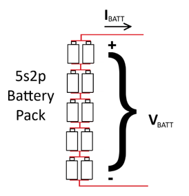
Figure 3: 5s2p Battery Back
Note that since the same current flows through the entire pack, the same number of parallel cells is required at every stage in the series.
Battery Capacity and Power
A battery cell’s capacity refers to the amount of electrical energy that a battery can store and deliver. Battery cell capacity can be specified in watt-hours (Wh), estimated with Equation (3):
$$CAPACITY_{CELL} = V_{CELL} \times I_{CELL} \times Runtime$$Capacity is commonly simplified as amp-hours (Ah), where VCELL is assumed based on the specific cell.
For simplification, the capacity of a battery pack can be determined by multiplying the total number of cells in the pack (both in series and parallel) by the capacity of a single cell. As long as all of the battery cells operate within the specified limits (e.g. temperature and current limits), higher-capacity packs provide a longer runtime than lower-capacity packs.
It is important to be able to fully use the available capacity within a battery to minimize system size and cost. To utilize the battery pack’s full capacity, the BMS monitors the key characteristics of the battery, such as SOC and state-of health (SOH). The accuracy of the BMS provides a direct tradeoff between the available capacity, safety, and lifecycle of the batteries. The BMS is responsible for ensuring the battery operates to its fullest extent, while not allowing it to operate in any state that would cause it to prematurely age or become unsafe.
Over time, all batteries see a reduction in capacity. In addition, overcharging or over-discharging a battery can reduce capacity. Consider your phone as an example. By overcharging or discharging your phone, you will reduce the battery’s capacity over time; this is why it is recommended to never let your phone discharge to 0% battery or charge up to 100% battery.
Power and Real-World Example
A battery pack’s available output power (POUT) is closely related to the battery pack’s capacity. A higher POUT means that the pack can supply more power and charge a receiving device more quickly.
The battery pack’s voltage and current determine the amount of available POUT, estimated with Equation (4):
$$P_{OUT} = V_{BATT} \times I_{BATT}$$From this equation, we can see that by increasing VBATT or IBATT, the pack’s POUT capability can be increased. This is an important when considering the power demand of the application. For example, smartphone batteries commonly require between 3.7V and 4.4V with a modest power demand, and laptops commonly require between 12V and 15V, with a much higher power demand.
Consider the battery pack inside of a portable heater that must deliver 288W of power. This heater is built with Li-ion battery cells that deliver up to 4A and a minimum of 3.6V. Each cell can deliver 14.4W (4A x 3.6V) of power. For a heater that requires 288W, the battery pack could have the following:
- 20 cells connected in series. If there are 20 cells in series, VBATT would be 72V (3.6V x 20). This would satisfy the POUT requirement of 288W (72V x 4A).
- 20 cells connected in parallel. If there are 20 cells in parallel, IBATT would be 80A (4A x 20), which would satisfy the POUT requirement of 288W (80A x 3.6V).
Although both configurations are capable of delivering 288W, there are significant tradeoffs to consider, such as safety when the pack voltage increases and loss of energy in cable and connector resistance as current increases.
Because batteries are costly, and they contribute significant size and weight to the end-product, it is not feasible to simply add extra cells to a pack to meet power and energy goals. Instead, the designer must determine the optimal cell configuration for the application.
Energy Density and Power Density
Energy density refers to the amount of energy that can be delivered from a battery per unit volume. A battery with higher energy density can operate equipment for longer than a battery with lower energy density.
Power density refers to the amount of continuous and peak power that can be delivered from a battery. A battery with higher power density can deliver more power than a less power-dense battery. Energy and power density do not directly affect the battery management system, but they are vital considerations when determining other factors that impact the BMS, such as the total number of series and parallel cells required to power the system.
Energy and power density can have a significant impact on the battery’s physical size and weight. This is often a key consideration, such as for mobile or portable applications. Higher-energy and power-dense batteries are the key to realizing small, lightweight designs. For example, a drone typically requires both high energy density for flight time and power density for lift; this functionality cannot be achieved with lead-acid batteries.
As a general rule, batteries with higher energy density and higher power density have an increased potential for thermal runaway or explosions, if not handled properly. Since Li-ion batteries contain very high energy and power density, they must be handled with care. This means that all battery cells within a battery pack must be carefully monitored to ensure proper operation, commonly handled by a battery monitor and protector device.
Battery Monitoring
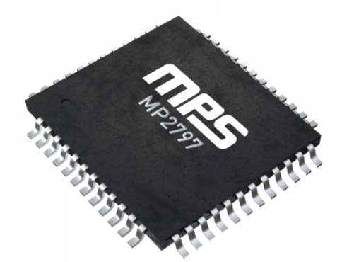
Consider the MP2797, a high-accuracy battery monitor and protector (see Figure 4). This device provides a complete analog front-end (AFE) solution designed for multiple-cell series battery packs, supporting 7 cells to up to 16 cells. The MP2797 provides over-voltage protection (OVP), short-circuit protection (SCP), under-voltage protection (UVP), and high/low temperature protection to ensure safety and reliability for each individual cell connected in series. These protections come with configurable thresholds.
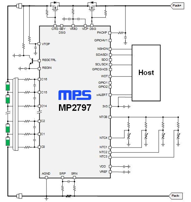
Figure 4: MP2797 Typical Application Circuit
The MP2797 integrates two analog-to-digital converters (ADCs). The first measures each cell’s voltage and temperature, while the second measures the charge/discharge currents to optimize charging and prolong the battery’s lifespan. An internal state machine works with the ADC to ensure the cell operates within the safe operating area (SOA) according to the thresholds. Lastly, balancing MOSFETs equalize the cell voltages to prevent battery stress.
These robust protections make the MP2797 well-suited for energy store systems (ESS), which provide electrical energy from a battery to supplement a high-energy source, such as an electrical grid. Using the MP2797, it is possible to create a BMS for an ESS to store excess energy, monitor the health of each battery cell, and provide status information in real time.
Battery Charging
In addition to maintaining a safe temperature range, a battery charger IC can be used to help maintain battery capacity by controlling the charge/discharge cycles. The MP2710 is a Li-ion battery charger with power path management (PPM) to ensure that there is continuous power to the system (see Figure 5). This is accomplished by taking power from the AC adapter or USB port.
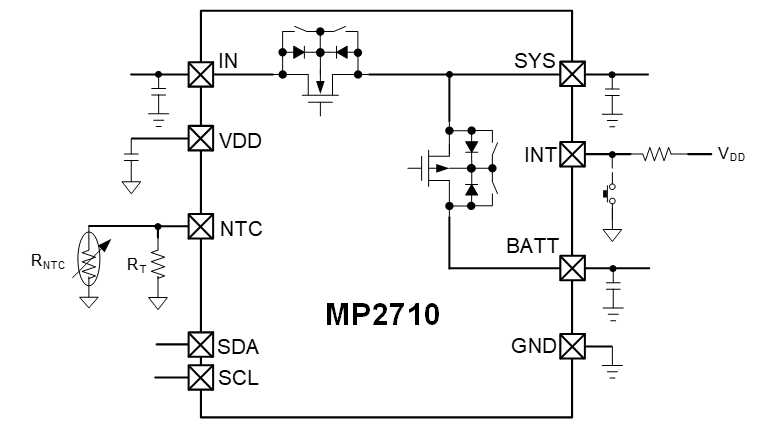
Figure 5: PPM for the MP2710
To prevent the battery from over-discharging, the MP2710 provides a configurable battery under-voltage lockout (UVLO), which cuts off the path between the system and battery if VBATT drops below its UVLO threshold. To protect the battery from an excessively high current, the MP2710 features short-circuit protection (SCP), which limits the current from the input to the system, as well as limits the current from the battery to the system.
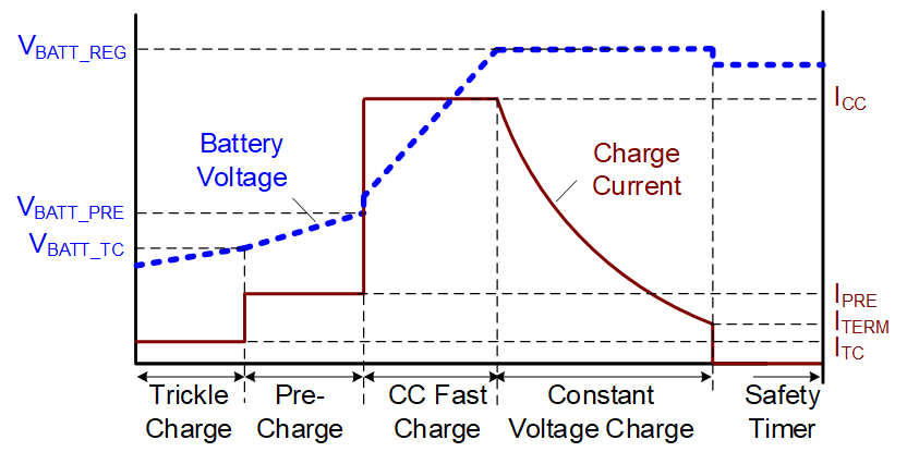
In addition, the MP2710 regulates the current and voltage through its charging profile, which includes pre-charge, constant-current (CC) fast charge, constant-voltage (CV) charge, charge termination, and auto-recharge. By intelligently cycling between these phases depending on the battery voltage and current, the MP2710 can protect the battery from damage and elongate its lifespan.
Conclusion
Batteries have a myriad of characteristics that impact how they can be used in a BMS. This article introduced battery chemistry, battery voltage, battery current, battery capacity, battery energy density and battery power density. These characteristics affect the battery management system by determining what chargers and controllers should be used, requiring certain protection functions, and even providing a greater POUT (and faster charging time).
In addition to battery selection, battery management systems can benefit from a battery protector and monitor that protects both the battery and the system from harmful conditions, as well as battery charger ICs that contribute to a battery’s long lifespan. MPS’ robust portfolio of these parts work with many different battery types to optimize every system.
_______________________
Did you find this interesting? Get valuable resources straight to your inbox - sent out once per month!
Technical Forum
 Latest activity 3 days ago
 5 Comments
Latest activity 4 days ago
2 Comments
Latest activity 5 days ago
14 Comments
5 Comments
Latest activity 4 days ago
2 Comments
Latest activity 5 days ago
14 Comments
Log in to your account
Create New Account