High-Power Battery Management System Solution Module
DOWNLOAD PRODUCT
BRIEF

Get valuable resources straight to your inbox - sent out once per month
We value your privacy
Overview
Introduction
The MBMxxS-P100-x is a complete solution for a 7-cell to 16-cell in series battery management unit with high currents.
This board uses the MP279x ICs, a robust family of battery management analog front-ends (AFEs) that provide a complete AFE monitoring and protection solution. The MP279x supports up to 16 cells in series, and provides two separate analog-to-digital converters (ADCs) for synchronous voltage and current measurements. The high-side MOSFET (HS-FET) driver and robust HW protection functions come with configurable thresholds. Protections include over-current protection (OCP), short-circuit protection (SCP), battery and cell over-voltage protection (OVP), battery and cell under-voltage protection (UVP), over-temperature protection (OTP), and under-temperature protection (UTP). The MP279x also integrates internal balancing FETs to equalize mismatched cells while offering the option to control external FETs for a higher balancing current.
The board also features the MPF4279x, a standalone battery fuel gauge (FG) IC that performs state-of-charge (SoC), time-to-full, time-to-empty, and unavailable energy estimation using a custom battery model obtained through exhaustive characterization and voltage, current, and temperature readings. This solution is fast, simple, and easy to configure through the graphic user interface (GUI). Figure 1 shows the MBMxxS-P100-x block diagram.

Figure 1: MBMxxS-P100-x Block Diagram Design
Each MBMxxS-P100-x solution offer different combinations of the MP279x AFE and the MPF4279x fuel gauge. See the Complete Solutions section on page 5 for more details.
Complete Solutions
| Solution | MPF4279x Part Number | MPF4279x Short Description | MP279x Part Number | MP279x Short Description |
| MBM16S-P100 | MPF42790 | 2-Cell to 16-Cell FG with Level LEDs | MP2797 | 7-Cell to 16-Cell BMS with I2C |
| MBM14S-P100 | MPF42790 | 2-Cell to 14-Cell FG with Level LEDs | MP2791 | 7-Cell to 14-Cell BMS with I2C |
| MBM10S-P100 | MPF42795 | 2-Cell to 10-Cell FG with Level LEDs | MP2791 | 7-Cell to 14-Cell BMS with I2C |
| MBM16S-P100-B | MPF42791 | Next Generation 2-Cell to 16-Cell FG with Level LEDs | MP2797 | 7-Cell to 16-Cell BMS with I2C |
| MBM14S-P100-B | MPF42791 | Next Generation 2-Cell to 14-Cell FG with Level LEDs | MP2791 | 7-Cell to 14-Cell BMS with I2C |
Kit Contents
MBM16S-P100
Items included with the kit (items below can be ordered separately):
| # | Part Number | Item | Quantity |
| 1 | BMU16S-P100-R01A | MP2797DFP-0001-T and MPF42790DR-0B-0001 or MPF42792-0B-0001 complete solution | 1 |
| 2 | EVKT-USB_RS485/I2C-01 | USB to RS-485/I2C adapter | 1 |
MBM14S-P100
Items included with the kit (items below can be ordered separately):
| # | Part Number | Item | Quantity |
| 1 | BMU14S-P100-R01A | MP2791DFP-0001-T and MPF42790DR-0B-0001 complete solution | 1 |
| 2 | EVKT-USB_RS485/I2C-01 | USB to RS-485/I2C adapter | 1 |
MBM10S-P100
Items included with the kit (items below can be ordered separately):
| # | Part Number | Item | Quantity |
| 1 | BMU10S-P100-R01A | MP2791DFP-0001-T and MPF42795DR-0B-0001 or MPF42797DR-0B-0001 complete solution | 1 |
| 2 | EVKT-USB_RS485/I2C-01 | USB to RS-485/I2C adapter | 1 |
MBM16S-P100-B
Items included with the kit (items below can be ordered separately):
| # | Part Number | Item | Quantity |
| 1 | BMU16S-P100-B-R01A | MP2797DFP-0001-T and MPF42791DR-0B-0001 complete solution | 1 |
| 2 | EVKT-USB_RS485/I2C-01 | USB to RS-485/I2C adapter | 1 |
MBM14S-P100-B
Items included with the kit (items below can be ordered separately):
| # | Part Number | Item | Quantity |
| 1 | BMU14S-P100-B-R01A | MP2791DFP-0001-T and MPF42791DR-0B-0001 complete solution | 1 |
| 2 | EVKT-USB_RS485/I2C-01 | USB to RS-485/I2C adapter | 1 |
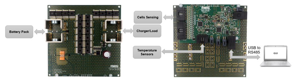
Figure 2: MBMxxS-P100-x Board Set-Up
Features and Benefits
- High-Side Charge and Discharge (Including Pre-Charge Function) MOSFETs
- 7 Cells, Up to 16 Cells in Series
- Up to 100A of Constant Charge/Discharge Current and Up to 150A of Peak Current
- True Hardware Protections
- 5V, CAN Bus and UART Availability for External Devices (e.g. Displays)
- External Fault Indicator LED and Pack Voltage Status LED
- High-Accuracy Analog-to-Digital Converter (ADC) with the Option of Simultaneous Voltage and Current Measurements
- Configurable Alarm Reactions and Thresholds:
- Configurable Over-Voltage Protection (OVP) and Under-Voltage Protection (UVP)
- Configurable Charge and Discharge Over-Current Protection (OCP) and Short-Circuit Protection (SCP)
- PCB and Configurable Battery Over-Temperature Protection (OTP)
- Self-Functionality Test Options
- Cell-Balancing with Internal MP279x FETs with Option of External Balancing FET for Higher Currents
- Open-Wire Detection
- Sleep Mode with Standby Discharge FET for Lower Current Consumption with Automatic Wake-p when a Load/Charger is Detected
- Load/Charger Detection Option in Safe Mode
- Accurate Battery Pack State-of-Charge (SoC) Estimate (see Figure 3)
- Simple Configuration through MPS’s GUI
- Supports any Lithium-Based Cell Type Using a Dedicated Battery Cell Model
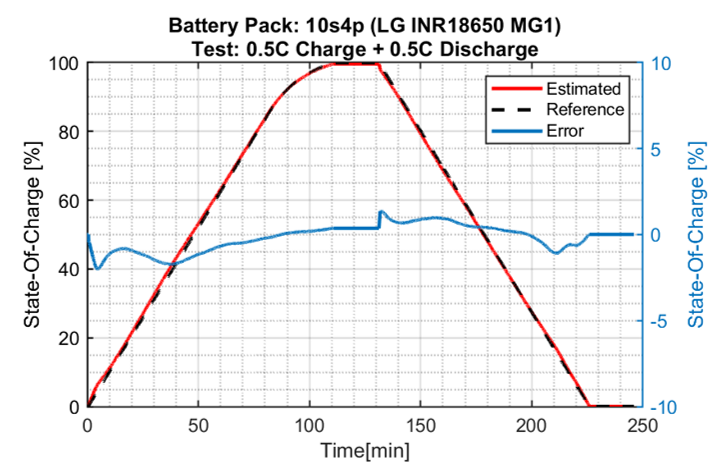
Figure 3: MBM16S-P100 Performance Example
Kit Specifications (1)
| Features | Specifications |
| Max series cell supported | MBM16S-P100-x: 16 cells in series MBM14S-P100-x: 14 cells in series MBM10S-P100-x: 10 cells in series |
| Battery pack voltage range | MBM16S-P100-x: 18V to 70.4V MBM14S-P100-x: 18V to 65.8V MBM10S-P100-x: 18V to 44V |
| Cell voltage range | Up to 4.5V (configurable cell UV and OV thresholds) |
| Charge current range | 0A to 196.605A (configurable charge OC threshold) (1) |
| Discharge current range | 0A to 196.605A (configurable discharge OC threshold) (1) |
| Total high-side protection resistance (connectors + PCB traces + 1 parallel FETs) | 4mΩ to 5mΩ |
| Operating systems supported | Windows 7 or later |
| System requirements | Minimum 350MB free |
| EVB size (L x W) | 123mm x 121mm (FETs board) 97mm x 61mm (control board) |
Note:
1) It is not recommended to exceed 120A of continuous current for the 10 parallel FET configuration. Up to 150A of peak current is supported.
Log in to your account
Create New Account