Designing a Power over Ethernet (PoE) Solution

Get valuable resources straight to your inbox - sent out once per month
We value your privacy
Power over Ethernet (PoE) is a power supply scheme that uses a network cable to transmit power. This scheme includes power sourcing equipment (PSE), a powered device (PD), and a network cable. With the popularity of IP device applications, PoE has become widespread among users due to its low installation costs, scalability, ease of management, and global compatibility.
After over a decade since the PoE IEEE 802.3af protocol was proposed in 2003, the maximum transmission power supported by PoE currently reaches 90W (IEEE 802.3bt). Figure 1 shows typical PoE applications, such as internet protocol (IP) phones, IP cameras, access points, and 5G indoor base stations.
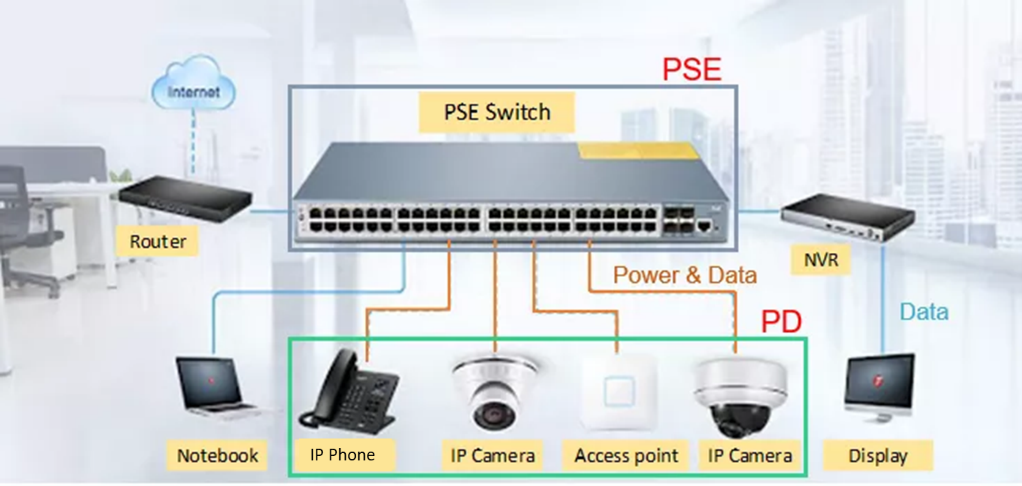
Figure 1: Typical PoE Applications
Due to the network cable structure and the application specifications, designers should meet the following conditions for their PoE solution:
- Select the correct circuit connection according to the PoE type, power transmission size, and appropriate physical connection method.
- Successfully match the protocol handshake, including the detection, power classification, and soft-start stages.
- Meet the minimum PSE power maintenance requirements. Ensure that the PD generates enough current signals for the PSE to maintain the power output and avoid false disconnection.
PoE Design
The PoE design consists of the protocol handshake for the PSE and PD, and the DC/DC transformation of the PD.
The circuit’s protocol handshake relies on a proprietary protocol industrial control system (ICS) using long distance and localized supervisory control, as well as data acquisition systems. By focusing on the DC/DC transformation of the PD, a PoE solution can be broken up into four parts: circuit topology, PoE size optimization, PoE efficiency, and an electromagnetic compatibility (EMC) problem analysis.
Circuit Topology
The cost of PoE applications depends on the type of circuit topology. Non-isolated topologies (e.g. IP phones and indoor IP cameras) are cost-effective, but there is a tradeoff, as they do not provide extensive security options. On the other hand, isolated class topologies (e.g. industrial AP or 5G small base systems) provide high safety, and are more common for outdoor or high-power applications (see Figure 2).
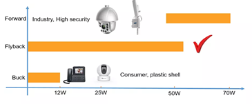
Figure 2: Tradeoff Between Different Circuit Topologies
PoE Size Optimization
For the most common reaction circuits, the power supply size can be minimized by increasing the switching frequency. In addition, designers can select continuous conduction mode (CCM) and the original edge feedback scheme with primary-side regulation (PSR) mode (see Figure 3).
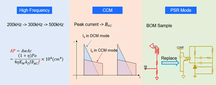
Figure 3: Using High Frequency, CCM, and PSR Mode to Minimize Power Supply Size
The MP8017 is an IEEE 802.3af-compatible PD with an integrated PD interface and a flyback converter. To optimize the device, the MP8017 provides primary-side regulation without needing auxiliary winding. It can also be set to secondary-side regulation for active-clamp flyback topologies. This device provides detection and classification. It also features a current limit, configurable soft-start time, EMI reduction with frequency dithering, and protections such as overload protection (OLP) and over-temperature protection (OTP). The MP8017 supports front-end solutions for PoE PD applications.
Increased Efficiency of PoE
The power loss of the reaction circuit is primarily concentrated in the power MOSFET, transformer, and diode. Figure 4 shows the loss generation analysis across the switch, conduction, transformer, and diode, and provides a series of optimization measures.
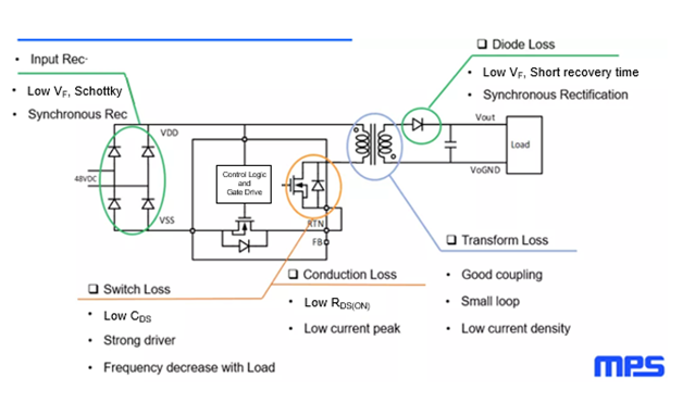
Figure 4: Analysis of Reaction Circuit’s Power Loss
EMC Problem Analysis
Two practical schemes can help address EMC issues. There can be EMI problems when multiple electronic devices adversely impact one another and create excessive field strength.
The first method to mitigate EMC issues is to decrease the switching speed, increase the absorption circuit, and shorten the high frequency circuit to reduce the noise source. The second method is to design the EMC filter to suppress noise transmission on the coupling path, as this inhibits the coupling path.
In addition, the control chip’s stabilization function is capable of significantly reducing the noise spike. Under the same conditions, converters with the stabilization function are more likely to meet EMC standards.
Conclusion
In this article, we discussed the general requirements of PoE and the design of the DC/DC transformation of the PD. MPS offers PoE power solutions for all the current protocol levels (af, at, and bt) featuring simplified BOM, efficient EMC characteristics, and other design advantages.
To learn more about PoE applications, read our Part I and Part II series on designing an active-clamp forward converter.
____________________________
Did you find this interesting? Get valuable resources straight to your inbox - sent out once per month!
Technical Forum
 Latest activity 14 hours ago
 1 Comment
Latest activity 9 hours ago
2 Comments
Latest activity a day ago
3 Comments
1 Comment
Latest activity 9 hours ago
2 Comments
Latest activity a day ago
3 Comments
Log in to your account
Create New Account