AN135 - DC Motor System Input Capacitor Recommendations And Discharge Circuit of MPQ6526 and MPQ6527 Family

Get valuable resources straight to your inbox - sent out once per month
We value your privacy
INTRODUCTION
For motor control system, when the motor speed decreases, the energy stored in the mechanical system or other inductive load may be recycled back through the motor driver to the DC power supply input rail. In real applications, it is necessary to add enough input capacitance to absorb this energy.
1. Ceramic Capacitor (Bypass Capacitor)
The ceramic capacitor is the supply bypass capacitor which should be a supply-rated X5R or X7R type, 0.1-µF ceramic capacitor must be placed as close to the device as possible which connected from the VIN pin (or VS, VM) to the PGND pin.
2. Bulk Capacitor
In addition, a bulk capacitor must be included on the VIN pin which is required to absorb the energy flowing from the motor or power supply and should be sized according to the application requirements
This application note describes the bulk capacitor recommendations and discharge circuit of MPQ6526 and MPQ6527 family. MPQ6526 and MPQ6527 family are multi- half-bridge DMOS output driver with integrated power MOSFETs, which support the application of H-bridges to drive DC motors.
RECYCLED MECHANICAL ENERGY FROM LOAS TO THE INPUT RAIL
When the motor speed decreasing or motion stopping, the motor works as a generator, which converts mechanical energy into electrical energy and need some path for current to flow. This energy would be mostly dissipated as heat or recycled back into the DC input rail.
1. Shorting the Output of the Motor
If a path is provided by shorting the output of the motor, which causes the motor to come to a stop. In this case, the energy is mostly dissipated as heat in the winding resistance of the motor and also in any resistance in the current path, shorting the motor.
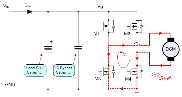
This short circuit is usually applied by turning on the low-side MOSFETs of an H-bridge to provide a current path.
2. Energy Flowing Back to Power Supply
When a control system wants to decrease the speed of the motor quickly, the polarity of the current applied to the motor is reversed to provide a torque in opposition to the motion, which is applied by turning on another diagonal pair of H-bridge or turning off all MOSFET (current will flow through body diodes). When this is done, the stored energy is driven back through the motor driver circuit into the power supply.
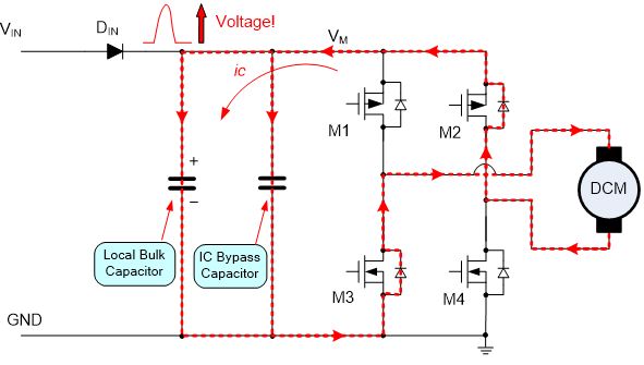
There are two sources of the energy flowing from motor: 1. remnant inductor current commutation, 2. BEMF. For the remnant inductor current—as seen in Figure 2 emanating from the commutation from M1/M4 to M2/M3—the current in the armature’s parasitic inductor does not dissipate immediately when M1/M4 is turned off. Thereafter the energy in the inductor flows back to the input capacitor through the body diodes of M2 and M3. The reverse BEMF current results from the motor speed switching from high to low: If the applied motor voltage drops (through the PWM or input) to drop the motor speed, the portion of the BEMF proportional to the motor speed will not change immediately, so the BEMF is bigger than the applied voltage. The energy reversal can charge the input capacitor and cause a voltage spike.
If the power source were a perfect battery, then energy would flow back into the battery and be recycled. However, the power source is usually a DC power supply, especially with an inverse-polarity protection diode, which can only source current and cannot sink current, the only place the energy has to go is into the bulk capacitance that is placed on the Vs power supply pin.
The amount of energy stored in the bulk capacitor can be calculated with ½ CV2, where C is the capacitance and V is the voltage. The voltage across the capacitor must increase as energy flows into it. So a bulk capacitor must be included on the VIN pin which is required to absorb the energy flowing from the motor or power supply and should be sized according to the application requirements.
If there is a lot of energy or not enough capacitance, the voltage may rise to exceed the maximum supply voltage limit (e.g. 40V of MPQ6526 and MPQ6527), damaging the motor driver IC or other circuitry connected to the same power supply.
POWER SUPPLY RIPPLE AND DISCHARGE CIRCUIT
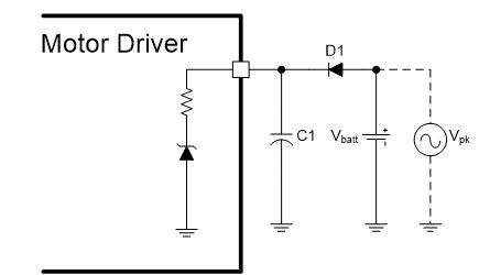
Many typical applications use an inverse-polarity protection diode, such as D1 in Figure 3. But, this method involves a certain danger. During inhibit mode, the IC consumes only an extremely low current IVS, such as 20 μA at maximum. Any peaks on the supply voltage will gradually charge the blocking capacitor. D1 prevents the capacitor from discharging via the power supply; due to the extremely small quiescent current, discharging via the IC can also be neglected. This means that during long periods in inhibit mode, the IC's supply voltage could increase continuously until the maximum supply voltage limit is exceeded, damaging the IC. So the MPQ6526 and MPQ6527 family feature a discharger circuit that prevents such unwanted effects. If VS exceeds a threshold value of approximately 37V, the blocking capacitor is discharged via an integrated resistor until VS again falls below the threshold.
INPUT CAPACITOR RECOMMENDATIONS FOR POWER SUPPLY PIN
Normally, a bulk electrolytic capacitor in parallel with a ceramic capacitor are recommended. A 100nF ceramic capacitor rated for power supply pin must be placed as close to the device as possible. Also, an appropriately sized bulk capacitor must be placed on the power supply pin, >22μF electrolytic capacitor was recommended, which is a recommended value, but system-level testing is required to determine the appropriate sized bulk capacitor.
The voltage rating for the bulk capacitors should be higher than the typical operating voltage, and provide a sufficient margin for cases when recycled energy flow back to the supply.
The Value for electrolytic capacitor needed depends on many factors including:
- External load
- The reverse-conducting current.
- The capacitance of the power supply to source current.
- The amount of parasitic inductance between the power supply and motor system, which will limit the current change rate from power supply. Larger input capacitance is used, the more stable the motor voltage and higher current can be quickly supplied.
- The maximum supply voltage limit and acceptable voltage ripple.
- The motor braking method, output short brake or current polarity reversing brake.
As Figure 2 shows, the recycled electrical energy charges the input capacitor. If there is insufficient capacitance on the DC input rail, a high-voltage spike occurs and may damage the power stage. If it is not practical to fit enough capacitance on the input rail, an OVP circuit can also be used to discharge the energy and limit the input rail voltage.
DESIGN SUMMARY
The energy recycled back into the input power supply causes a voltage spike and potential risk. It is necessary to add enough input capacitance to absorb this energy. The sufficient input bulk capacitance is important in motor drive system design. It is beneficial to have more bulk capacitance, while the disadvantages are increased cost and physical size. This application note should help you understand how the energy can be flow back to power supply and why we need to use sufficient bulk capacitor. The math required to determine the component values for a given system properly is beyond the scope of this article, but more details, including calculations for capacitance and clamp components, are provided in the application note AN132 “Input Capacitor and Over-Voltage Protection Circuit Design”.
_______________________
Did you find this interesting? Get valuable resources straight to your inbox - sent out once per month!
Technical Forum
 Latest activity 7 days ago
 2 Comments
Latest activity a week ago
2 Comments
Latest activity 4 weeks ago
1 Comment
2 Comments
Latest activity a week ago
2 Comments
Latest activity 4 weeks ago
1 Comment
Log in to your account
Create New Account