Bipolar Stepper Motors (Part I): Control Modes

Get valuable resources straight to your inbox - sent out once per month
We value your privacy
Introduction
In the intelligent era, stepper motors are widely used due to their unique open-loop position control performance. Each device has specific requirements that ensure there is a smooth output torque while the stepper motor rotates. Rotation stability is closely related to the motor’s physical construction as well as its control mode.
This article introduces the bipolar stepper motor and discusses its structure and control modes.
Basic Components of a Bipolar Stepper Motor
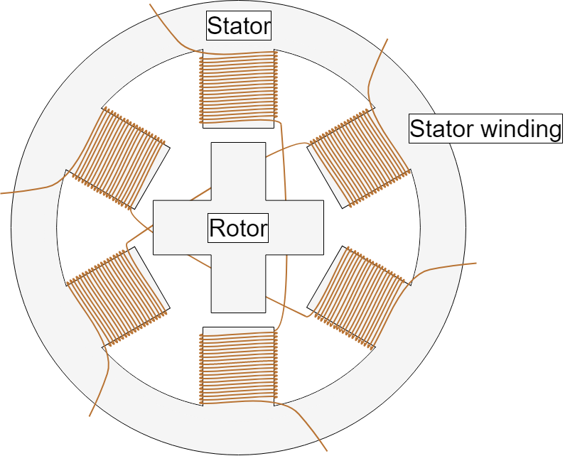
Stepper motors are brushless DC (BLDC) motors that divide their rotation into equal steps. A bipolar stepper motor is a type of stepper motor that has a single winding per phase. Bipolar stepper motors are two-phase, four-wire stepper motors. They are comprised of two primary components: the stator and rotor (see Figure 1).

Figure 1: Bipolar Stepper Motor Structure
Stator
The stator is the stationary part of the motor. The windings are wound on 8 stators, and each stator core has five teeth (see Figure 1).
Phase A’s windings start from stator 1, then winds to stator 3, stator 5, and stator 7 (see Figure 2). Note that the winding directions of stator 1 and stator 5 are the same, while the winding directions of stator 3 and stator 7 are the same. These two groups (stator 1 and stator 5, then stator 3 and stator 7) wind in opposite directions. Phase B’s windings are based on the same principle, with stator 4 and stator 8 consisting of a group, and stator 2 and stator 6 consisting of a group.
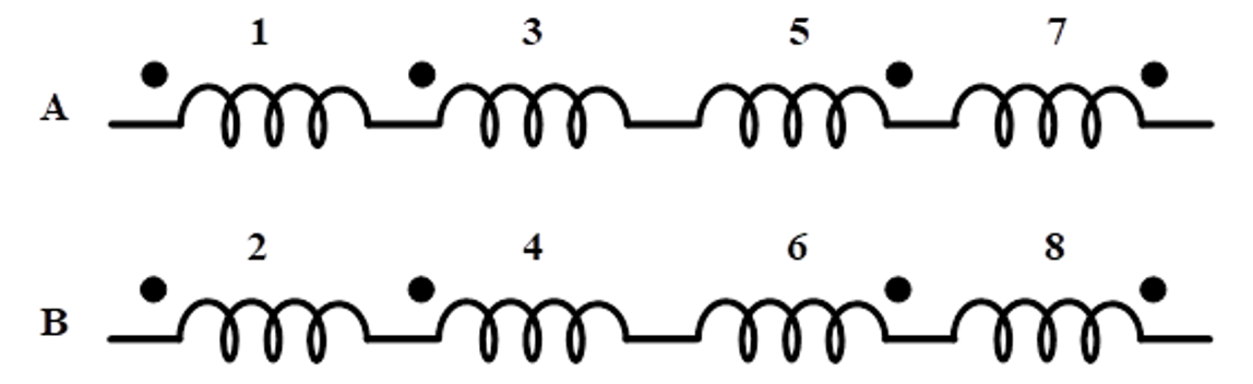
Figure 2: Bipolar Stepper Motor Winding Schematic
Rotor
The rotor is typically attached with an axially magnetized permanent magnet. Figure 3 shows the rotor structure.

Figure 3: Rotor Structure
Figure 4 shows the rotor side’s cross-sectional view.

Figure 4: Side Cross-Sectional View
The permanent magnet’s magnetic line of force forms a closure in the motor body. Due to the magnetic line of force and magnetoresistance effect, the stepper motor has a certain locking torque even when it is not energized (see Figure 4).
The rotor has 50 teeth opposite to the stator gear and a step angle of 1.8 degrees due to the number of teeth and phase structure (see Figure 5). The stepping angle is defined as the mechanical angle at which the stepper motor rotor moves forward when the electrical cycle is completed by 90 degrees.
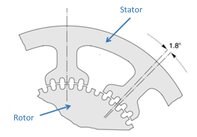
Figure 5: 1.8° Step Angle
Related Content
-
WEBINAR
Stepper Motors and Back EMF
Learn about Electro Motive Force (EMF), it's impact on motion in a stepper motor, and more
-
ARTICLE
Stepper Motors Basics: Types, Uses, and Working Principles
Understand the basics of stepper motors
-
VIDEO
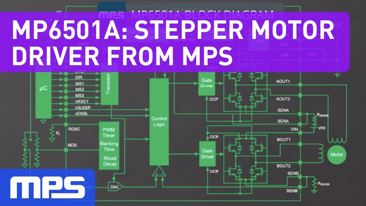
Stepper Motor Driver from MPS
Learn more about our integrated bipolar stepper motor driver with micro-stepping function
-
APPLICATION BLOCK
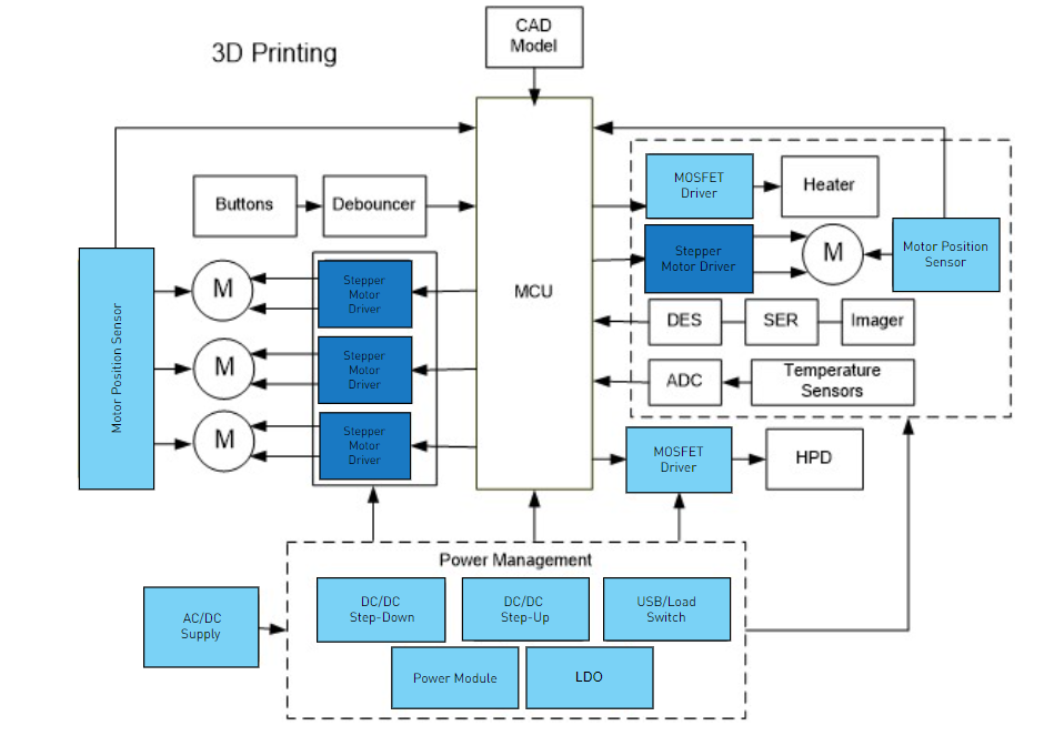
3D Printers
MPS solutions offer the best options to design the next generation of 3D printers
Stepping Modes
The bipolar stepper motor’s structure can be simplified to better understand the subsequent control methods (see Figure 6).
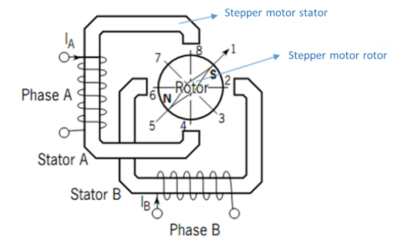
Figure 6: Simplified Schematic of a Bipolar Stepper Motor
The stator and rotor can be considered to only have one tooth, which drives the stepper motor differently from other motors. This is called a dual full-bridge drive, where the phase A winding is connected to the first full-bridge drive, and the phase B winding is connected to the second full-bridge drive (see Figure 7).

Figure 7: Dual Full-Bridge Driver Circuit Diagram
The bipolar stepper motor has three control modes: a single-phase step, full step, and half-step (see Table 1).
Table 1: Stepper Motor Control Modes
| Stepping Mode | Sequence | Electrical Stepping Position |
| Single-phase step | $$A > B > \overline{A} > \overline{B}$$ | $$8 > 2 > 4 > 6$$ |
| Full step | $$AB > \overline{A} B > \overline{AB} > A \overline{B}$$ | $$1 > 3 > 5 > 7$$ |
| Half-step | $$AB > B > \overline{A} B > \overline{A} > \overline{AB} > \overline{B} > A \overline{B} > A$$ | $$1 > 2 > 3 > 4 > 5 > 6 > 7 > 8$$ |
Single-Phase Stepping
When phase A and phase B are driven in sequence according to the single-phase stepping mode, the stator magnetic field changes, and the rotor rotates due to polarity attraction. See Table 1 for phase A and phase B’s (AB) energization sequence and the rotor’s rotational position.
The single-phase stepping process occurs in three steps, described below:
- When phase A is driven, the drive current flows from Q1 to Q4. During this time, the upper end of stator A is at N, the lower end of stator A is at S, and the rotor turns to position 8 (see Figure 6).
- Next, phase B is driven, and the drive current flows from Q5 to Q8. One end of stator B is S, the other end of stator B is N, and the rotor turns to position 2 (see Figure 6).
- During the next two states, the rotor starts to rotate after cycling the start-up sequence.
Figure 8 shows phase AB’s current waveform during single-phase stepping.
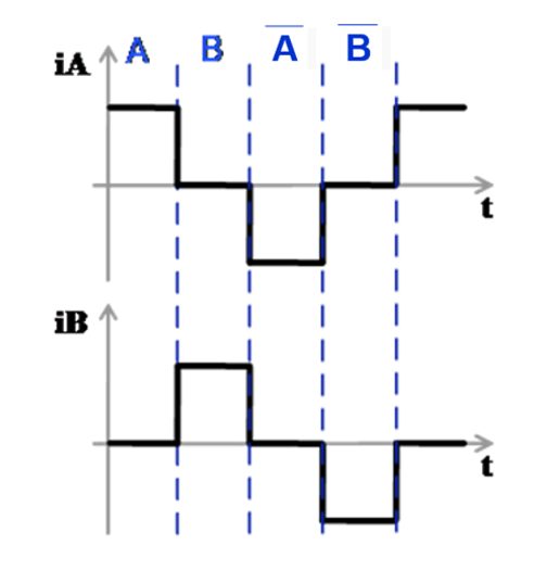
Figure 8: Phase AB’s Single-Phase Stepping Current Waveform
Full-Step Stepping
Unlike single-phase stepping, the winding for both phase A and phase B are driven simultaneously during full-step mode. There are also four corresponding energization modes and rotor electrical positions, where the position space differs from single-phase stepping in the electrical space. The rotor can rotate based on the device’s start-up sequence. Figure 9 shows the phase AB’s full-step current waveform.
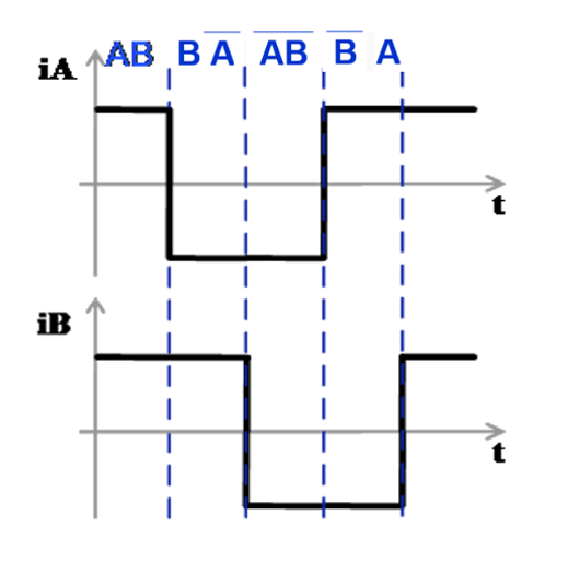
Figure 9: Full-Step (Phase AB’s Current Waveform)
Half-Step Stepping
In half-step mode, both single-phase and full-step stepping work together to offer more electrical angle positions, detailed current waveforms, and smoother rotation.
Figure 10 shows non-circular, half-step mode for one-phase to two-phase operation. This mode alternates between full step and half-step to generate an 8-step sequence.
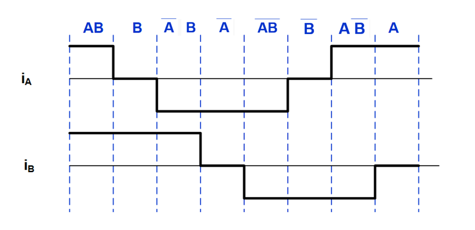
Figure 10: Non-Circular Half-Step Mode
Conclusion
This article reviewed the basic components of a bipolar stepper motor (the stator and rotor), as well as the three primary control modes: single-phase, full-step, and half-step stepping. Part II will discuss microstepping for the dual full-bridge drive.
MPS offers a wide array of stepper motor drivers to meet your application needs.
_______________________
Did you find this interesting? Get valuable resources straight to your inbox - sent out once per month!
Technical Forum
 Latest activity 6 days ago
 2 Comments
Latest activity a week ago
2 Comments
Latest activity 4 weeks ago
1 Comment
2 Comments
Latest activity a week ago
2 Comments
Latest activity 4 weeks ago
1 Comment
Log in to your account
Create New Account