E-Tracker Reference Design: Automotive Tracker with Linear Charger
DOWNLOAD THE FULL REFERENCE DESIGN

Get valuable resources straight to your inbox - sent out once per month
We value your privacy
1.1 Description
Tracking the location of different types of vehicles is an increasingly popular application for multiple purposes, such as control of transport trucks or anti-theft security. However, this presents two challenges in electronic design. First, the system must be able to track a vehicle’s location when the car battery is turned off. Second, the GSM modules that establish communication with the receiver station have strict operating input voltage ranges.
The first challenge of this design is to maintain communication when the car battery is off. The solution presented in this reference design consists of adding an external Li-ion battery pack, that supplies the required power to the GSM module when the car battery is turned off, and a battery charger to maintain the battery charge. For example, if a car battery supplies 12V, the battery charger and the GSM module receive power from the battery, and the external battery enters in charging mode. When the car battery is disconnected, the external battery pack supplies the power to the GSM module.
The second challenge consists of adjusting the input voltages of the battery charger and the GSM module while considering their specifications. Generally, GSM modules have an operating input voltage range between 3.4V and 4.2V, while the battery charger voltage ranges between 4.05V and 6.05V. This means that a buck converter is required to decrease the input voltage from 12V (car battery) to 4.2V. On the other side, it is also needed to protect the GSM module from load transients. Because of this, a diode is added to decrease the voltage at the buck’s output below 4V.
This reference design will help engineers design a simple power stage for a common e-tracker that can track the location of different vehicles.
1.2 Features
- Wide 4.2V to 36V Operating Input Range
- 3A Continuous Output Current
- 350kHz to 2.5MHz Configurable Buck Switching Frequency
- Second-Order EMI Filter
- Reverse Polarity Protection
- Fully-Autonomous Charger
- Configurable 30mA to 1A Charge Current
1.3 Applications
- Car Tracking
- Internet Connectivity
- 2G Communications (Calls, SMS and MMS)
- Telematic Services
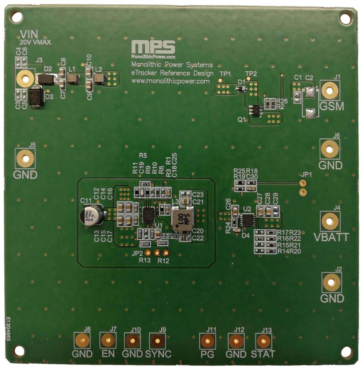
Figure 1: MPS E-Tracker Reference Design Board
Reference Design
2.1 Block Diagram
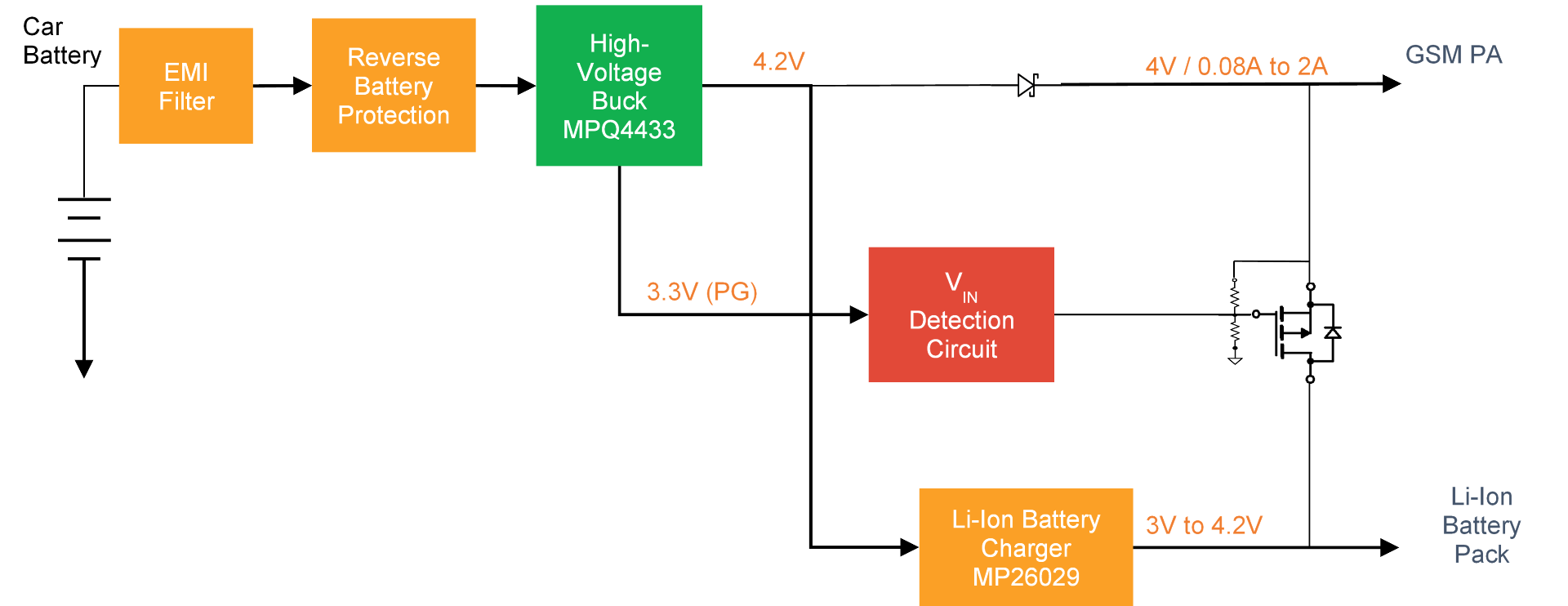
Figure 2: Block Diagram
The circuit contains five main blocks. First, a buck converter reduces the supply voltage from 12V (supplied by the car battery) to a stable 4.2V. The design limits the input voltage to 36V (due to the selected step-down converter specifications). However, the design can be modified to reach higher input voltages without significant alterations to the PCB design. Second, a Li-ion battery charger maintains the charge of the external battery pack. Third, the VIN detection circuit detects the state of the car battery to activate the Li-ion battery pack supply. Finally, the EMI filter and the reverse battery protection feature protect the circuit from suboptimal operation.
2.2 Related Solutions
This reference design is based on the following MPS solutions:
| MPS Integrated Circuit | Description |
| MPQ4433 | Synchronous buck converter with a wide input voltage range and up to 3A of output current |
| MP26029 | Li-ion/Li-polymer battery charger IC with thermal regulation |
Table 1: System Specifications
2.3 System Specifications
| Parameter | Specification |
| Input voltage range | 4.2V to 36V |
| Output voltage range | 3.3V to 4.1V |
| Nominal load | 4V/80mA |
| Maximum Peak Output Current(1) | 3000mA |
| Switching frequency | 450kHz (under nominal conditions) |
| Board form factor | 100mmx100mmx2mm |
| Converter efficiency (VIN = 12V) | 94% |
| 4V output ripple | 31.25mV |
| Load transient (2A to 80mA) | 270mV |
| Charge current range | 30mA to 1A (set to 110mA) |
| Battery voltage | 3.6V to 4.2V (set to 4.2V) |
| VIN quiescent current (ILOAD = 0A) | 700µA |
| Li-ion battery quiescent current | 45µA |
| Shutdown current (MPQ4433 off) | 2µA |
Table 2: System Specifications
Test Results
3.1 Efficiency and Regulation
VOUT = 4.2V, L = 8.2µH, fSW = 454kHz, TA = 25°C.

Figure 10: Efficiency vs. Load Current – Buck Converter

Figure 11: Efficiency vs. Load Current – System without Battery
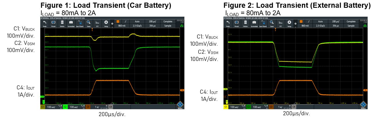
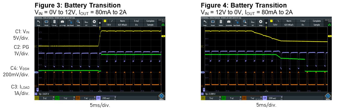
3.2 Time Domain Waveforms
VIN = 12V, VOUT = 4.2V, L = 8.2µH, fSW = 454kHz, TA = 25°C.
3.3 EMC Measurements
VIN = 13.5V, VOUT = 4.2V, L = 8.2µH, COUT = 30µF, fSW = 454kHz, TA = 25°C.
150kHz to 108MHz

Figure 33: CISPR25 Class 5 Conducted Emissions
150kHz to 30MHz

Figure 34: CISPR25 Class 5 Radiated Emissions
Log in to your account
Create New Account