AN216 - Brushless DC (BLDC) Motor Phase Undershoot

Get valuable resources straight to your inbox - sent out once per month
We value your privacy
Introduction
In brushless DC (BLDC) motor drive circuits, parasitic inductances on the PCB can often result in the motor phase nodes being driven to a negative voltage for a short period of time during switching. This issue is worse with high-current, low-inductance motors, where the dI/dt during switching can be very high.
MPS’s BLDC pre-drivers, such as the MP653x family, are tolerant of negative transients on the phase nodes. However, in extreme cases, negative transients can damage the device.
Cause of Undershoot
Consider driving current into a motor. When the high-side MOSFET (HS-FET). switches off, current must continue to flow in the same direction due to the inductive nature of a motor. Initially, the recirculation current flows though the body diode of the low-side MOSFET (LS-FET). In most drivers, the LS-FET then turns on.
The body diode eventually clamps the voltage at a diode drop below ground. However, the recovery characteristics of the body diode, paired with the parasitic inductances of the PCB, combine to create a negative undershoot at the phase node (SHx) (see Figure 1).
A high current, as well as the high dI/dt caused by low motor inductance, exacerbate this negative undershoot.

Figure 1: Negative Undershoot
MPS's Gate Driver Negative Voltage Tolerance
MPS’s gate driver ICs are designed to tolerate negative undershoot on the phase node (SHx). Refer to the related datasheet for the absolute maximum ratings for the specification.
In addition to the phase node, consider what happens to the bootstrap pin (BSTx). Since there is a capacitor between BSTx and SHx, a large negative undershoot on SHx can also force the BSTx pin to experience an excessive voltage relative to SHx, or to be driven to a negative voltage. A large bootstrap capacitance can increase the amount of undershoot, which can damage the IC.
Mitigation Techniques
Generally, with a good PCB layout, there are no other considerations that must be made, as the negative undershoot stays within the IC’s transient absolute maximum ratings. In some cases, especially those with low-inductance / high-current motors, additional protection may be required.
The recommended mitigation technique is to insert a small series resistance (typically 10Ω) in series with the connection to the SHx pin of the IC, and add a Schottky diode from SHx to ground. Note that the resistance must be kept quite small (e.g. below 22Ω), as it is placed in series with the high-side gate charge current.
Figure 2 shows where to place the Schottky diode on SHx.
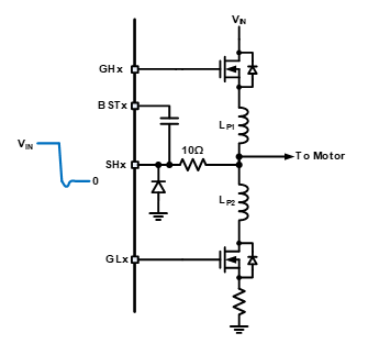
Figure 2: Schottky Diode on SHx
When subjected to repetitive negative undershoot on SHx, the bootstrap capacitor can be charged to an excessive voltage. This over-voltage condition can damage the bootstrap circuit, or even cause a breakdown of the HS-FET gate when the SHx output is driven high. In this scenario, it is possible to connect a transient-voltage-suppression (TVS) diode between BSTx and SHx.
The TVS diode should be rated to break down above the maximum HS-FET gate drive voltage. For the MP653x devices, a 12V TVS diode is recommended. The TVS diode clamps the voltage between BSTx and SHx to avoid exceeding the internal bootstrap circuit's breakdown voltage.
It is recommended to place a Schottky diode on SHx instead of a TVS diode on BSTx; with a solution using a TVS diode, the BSTx pin can be subjected to a negative voltage in extreme cases of SHx undershoot.
Figure 3 shows a solution with a TVS diode.
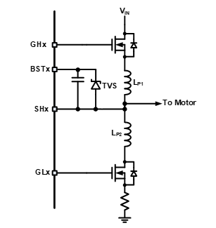
Figure 3: TVS Diode between BSTx and SHx
_______________________
Did you find this interesting? Get valuable resources straight to your inbox - sent out once per month!
Technical Forum
 Latest activity 5 days ago
 2 Comments
Latest activity 6 days ago
2 Comments
Latest activity 3 weeks ago
1 Comment
2 Comments
Latest activity 6 days ago
2 Comments
Latest activity 3 weeks ago
1 Comment
Log in to your account
Create New Account